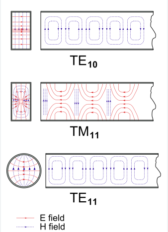
6 Reasons TM01 and TM10 Modes Can’t Exist in Rectangular Waveguides
TM01/TM10 modes cannot exist in rectangular waveguides because their field equations require zero longitudinal electric field (Ez=0) at all boundaries, which is impossible given the waveguide’s width (a) and height (b) dimensions. The Helmholtz equation solutions demand m,n≥1 for TM modes, making TM00 mathematically invalid. Cutoff frequencies (fc= c/2√[(m/a)²+(n/b)²]) become undefined when m or n=0, […]
6 Reasons TM01 and TM10 Modes Can’t Exist in Rectangular Waveguides Read More »