
Choose a manual waveguide switch for occasional, accessible changes. Choose an electric switch when the RF path must change remotely, automatically or within a measured time limit. Neither actuation method guarantees lower loss or longer life. Compare the actual RF specifications, switching conditions, feedback and endurance test for the selected model.
| Requirement | Selection consequence |
|---|---|
| Infrequent changes beside the equipment | Manual operation can avoid an actuator supply and controller, if the handle remains accessible. |
| Unattended operation or automatic redundancy | Electric actuation needs a compatible controller, position feedback and a defined response to faults. |
| A tight interruption-time limit | Measure the complete changeover, including RF muting, motion, confirmation and recovery. |
| High switching frequency | Specify the number of operations, RF loading and acceptable performance after endurance testing. |
Control: local access or an automatic RF path
Table of Contents
What manual operation removes—and what it does not
A manual switch moves its RF routing mechanism through a handle or knob. It does not need electrical power for that movement, although a particular assembly may still contain position sensors or an interlock. Loss of actuator power therefore need not prevent a manual change; it does not mean the transmitter, receiver or complete link can operate without power.
Check the handle clearance, operating torque, position markings and access with the equipment installed. A switch inside a locked or inaccessible enclosure may be unsuitable for a recovery procedure that requires an immediate change.
Specify the port map as well as the handle position. For SPDT routing, identify the common port and each selectable path. For DPDT routing, record both connections in every position; the label alone does not replace the manufacturer’s port diagram.
What an electric switch needs
An electric switch adds an actuator and its drive circuitry. The command may use discrete logic, a relay interface or a communications controller, depending on the assembly. Confirm supply voltage, startup current, command levels, connector pinout and feedback signals before wiring it into a PLC or test system.
Dolph’s published double-ridged waveguide switch table lists latching SPDT and DPDT models with 22–32 VDC actuator power. It lists 120 ms for the WRD350 rows and 80 ms for the WRD650 rows. These are model-specific published values, not universal limits for electric switches. Confirm the current drawing and timing definition for the ordered part.
RS-485 identifies an electrical interface; it does not by itself establish that a controller implements Modbus. The Modbus Organization distinguishes the application protocol from its underlying physical network. For a Modbus implementation, obtain the register map, serial settings, command behavior and error responses.[1]
Do not assume a catalog switch includes a network interface simply because an external controller can provide one. A complete quotation should identify which functions belong to the switch, its driver and the system controller.
Position feedback and loss of power
Separate three states in the control logic: command received, mechanism at the requested position, and RF path verified. An acknowledgement confirms the first state. A position sensor can confirm the second. Neither alone measures insertion loss, isolation or VSWR.
A latching design is intended to retain its selected position without continuous holding power. A failsafe design is intended to return to a designated position when drive power is removed. Confirm the actual power-loss behavior, startup state and recovery sequence; also test loss of power during movement.
Motor-current monitoring may detect a stall. It does not measure reflected RF power. Automatic protection against excessive reflected power needs a suitable RF measurement path and a defined interlock response.
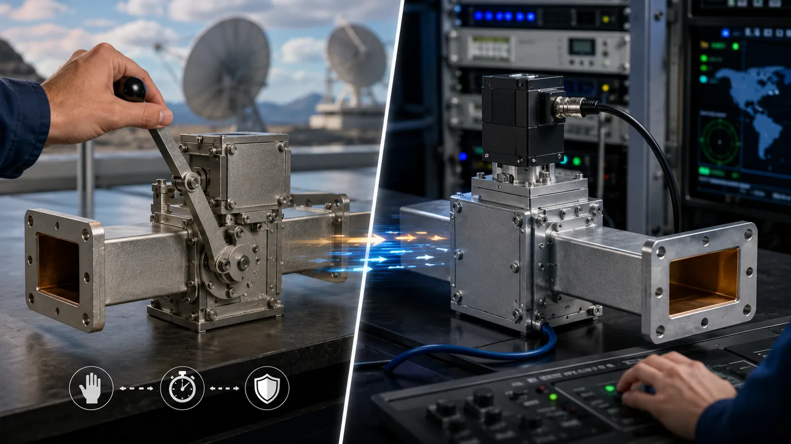
Speed: measure service interruption, not just actuator motion
Manual changeover time includes operator response, access, movement and verification. There is no defensible universal “2–3 seconds” rating for that process. Electric operation removes the need for an operator at the switch, but command latency and system sequencing still contribute to the interruption.
For sequential steps, use ttotal = tcommand + tmute + tmotion + tconfirm + tsettle + trestore. If steps overlap, measure the actual sequence rather than adding overlapping intervals twice.
Illustrative timing budget: a 500 ms actuator step plus 700 ms of other sequential delays produces a 1.2-second interruption. This is arithmetic, not a measured Dolph switching result. A published 80 ms or 120 ms switch time cannot, by itself, prove that an entire redundant link recovers within that period.
Keep RF power off during movement unless hot switching is rated
Cold switching means changing the path with RF power removed. Hot switching means changing it while RF power is present. A switch’s steady-state power rating does not establish its hot-switching capability.
Unless the selected model explicitly supports the required hot-switching conditions, use this sequence:
- Inhibit the RF source and verify the required safe state.
- Command or manually move the switch.
- Confirm the destination position and wait the specified settling interval.
- Restore RF only after the permitted path is established.
Apply the same logic to manual operation where the system needs an interlock. The power-handling specification should separately state CW or average power, peak power, pulse timing, pressure and allowable mismatch.
Reliability: compare evidence under the same duty
Count operations before comparing life claims
Manual and electric switches both contain mechanical parts that can wear or lose alignment. Electric models add actuator, wiring and controller failure modes. Manual operation adds dependence on access, correct positioning and operator response. Fewer electronic parts alone do not establish better system availability.
Calculate the required operation count from the intended schedule. One change every 5 seconds for 72 hours is 51,840 movements. If one endurance cycle means an A-to-B-to-A round trip, that is 25,920 cycles. Confirm how the supplier defines a cycle before comparing a quoted life value with the application.
Request the test sample count, movement rate, temperature, RF state, load conditions and failure criterion. A no-load mechanical endurance result does not demonstrate the same endurance under hot switching. A headline such as “100,000 cycles” is incomplete without those conditions.
MTBF is not a wear-out deadline
Do not read a stated MTBF as the number of hours every switch will survive. Ask whether it is predicted or measured, which components it covers, and which failure-rate model and operating conditions were used.
NIST describes the exponential reliability model as having a constant failure rate and notes its suitability when early failures and wear-out are not the concern. That assumption does not replace a mechanical endurance test for a repeatedly operated switch.[2]
Check RF performance after repeated movement
Measure insertion loss, return loss or VSWR, isolation and position repeatability over the specified band, both initially and after the agreed endurance exposure. In a phase-sensitive system, add phase repeatability at defined frequencies and reference planes.
For a real reference impedance, the reflected-power fraction is [(VSWR − 1)/(VSWR + 1)]². A change from VSWR 1.15 to 1.48 corresponds to approximately 0.49% to 3.75% reflected power. These are calculated examples, not an observed wear test. They do not establish insertion loss, because reflected power and dissipated power are different quantities.
Keep the flange alignment and VNA calibration consistent when comparing measurements. Record the test setup and uncertainty; a changed connection can obscure whether the switch itself has drifted.
Match environmental tests to the installation
State operating temperature, humidity, condensation, vibration and corrosion exposure separately. The controller and actuator may have different limits from the passive RF body. Confirm lubrication and startup behavior at the lowest specified temperature.
A 48-hour or 96-hour salt-spray result is an exposure duration, not a conversion into years outdoors. ISO 9227 defines salt-spray methods but leaves product-specific exposure and interpretation to the applicable specification; it does not use these tests to predict long-term corrosion resistance.[3]
What to put in the purchase and acceptance specification
- RF path: frequency band, waveguide size, flange drawing, port map, insertion loss, VSWR and isolation for each selected position.
- Power: CW, average and peak conditions, permitted mismatch, and whether movement occurs with RF off or on.
- Control: manual access or electrical interface, supply limits, feedback, power-loss behavior and timeout response.
- Timing: start and end events for the switch-time measurement, plus the complete system interruption limit.
- Life and environment: required movements, cycle definition, temperature and exposure conditions, and RF limits after testing.
- Evidence: serial-number-linked measurements and the agreed test conditions in the component acceptance report.
For a custom switched waveguide assembly, send the routing drawing and allowed interruption time with the RF requirements. Ask Dolph to identify the proposed switch, driver and verification scope, including any functions the external controller must supply.