
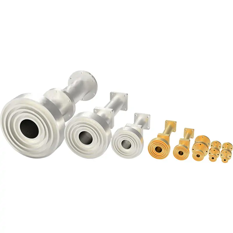
Microwave Feedhorn
Microwave feedhorns are specialized antennas designed for focusing and directing microwave signals into or out of transmitting equipment. They play a crucial role in satellite communication, radio telescopes, and radar systems by ensuring efficient signal collection and transmission, optimizing system performance across various microwave frequencies.
Precision Feed Solutions for Reflector Antenna and Microwave Systems
Introducing the Dolph Microwave Feedhorn, a cutting-edge solution designed for the precise focusing and directing of microwave signals. Engineered with meticulous attention to detail, this feedhorn covers a wide range of frequency bands including C, X, Ku, and Ka, ensuring versatility across numerous microwave communication applications. Constructed from high-quality aluminum or copper, the Dolph Microwave Feedhorn is synonymous with durability and high performance. Available in both standard and customized configurations, it meets the diverse needs of modern satellite communication, radar systems, and radio telescopes.
Key Features
The feedhorn configuration should be matched to the operating band, reflector geometry, polarization requirement, waveguide interface and target radiation performance of the complete antenna system.
- Wide Frequency Coverage: Supports C, X, Ku, and Ka bands, catering to a broad spectrum of microwave communication needs.
- Advanced Polarization Options: Offers Linear/Circular, Dual, or Co-polarization, enhancing signal clarity and reducing interference.
- Exceptional VSWR: Boasts a Voltage Standing Wave Ratio (VSWR) of 1.2:1, indicating minimal signal reflection and maximum transmission efficiency.
- Premium Material Construction: Precision machined from Aluminum (Al) or Copper (Cu), ensuring robustness and longevity.
- High Performance: Designed for superior signal focusing and direction, optimizing the efficiency of microwave transmission systems.
- Customization Availability: Provides options for both standard and tailored designs to perfectly fit specific system requirements.
- Ease of Integration: Engineered to seamlessly integrate with existing microwave transmission equipment, simplifying setup and installation.
How a Feedhorn Supports Antenna Performance
A feedhorn forms the RF transition between a waveguide or feed network and free space. In reflector antenna assemblies, its geometry and position influence how energy illuminates the reflector, how efficiently the aperture is used and how unwanted spillover is controlled.
Transmit Operation
The feedhorn converts guided microwave energy into a controlled radiated field directed toward the reflector or target coverage region.
- Supports controlled reflector illumination.
- Provides the required polarization at the antenna feed point.
- Connects to the selected waveguide or feed-network interface.
Receive Operation
The feedhorn collects microwave energy from the reflector and couples it into the receiving waveguide chain with the required impedance and polarization characteristics.
- Supports efficient signal collection.
- Helps control cross-polarization and spillover performance.
- Integrates with OMT, polarizer, filter or receiver assemblies as required.
Define the Band
State the exact transmit and receive frequency ranges rather than only the general band designation.
Match the Reflector
Provide reflector type, focal ratio, feed position and required illumination or edge-taper target.
Confirm the Interface
Specify waveguide size, flange type, polarization orientation and the available mechanical envelope.
Application Areas
- Satellite Communication: Vital for transmitting and receiving signals in satellite communication systems, ensuring global connectivity.
- Radar Systems: Enhances radar signal direction and focus, crucial for accurate detection and tracking in defense and weather forecasting.
- Radio Telescopes: Plays a key role in focusing signals for radio astronomy, enabling the study of celestial phenomena.
- Wireless Communication: Improves signal direction and focus in wireless communication networks, enhancing data transmission reliability.
- Broadcasting: Essential for focusing signals in broadcasting systems, ensuring clear transmission of audio and video content.
Technical Specifications
To provide a clearer understanding of the Dolph Microwave Feedhorn’s capabilities, here is a brief overview of its technical specifications:
| Specification | Details |
|---|---|
| Frequency Bands | C, X, Ku, Ka |
| Polarization | Linear/Circular, Dual, Co-polarization |
| VSWR | 1.2:1 |
| Material | Aluminum (Al), Copper (Cu) |
This table underscores the precision engineering and performance capabilities of the Dolph Microwave Feedhorn, highlighting its adaptability to various system requirements.
Published Feedhorn Configuration Examples
The following rows consolidate representative configurations shown in the downloadable Dolph Microwave Feedhorn catalog. They are useful for preliminary comparison and do not replace a model-specific quotation or approved technical drawing.
| Band | Published Frequency Range | VSWR | f/D | Taper | Half Illumination Angle | Cross Pol. | Horn Diameter | Interface | Antenna Type |
|---|---|---|---|---|---|---|---|---|---|
| S | 2.025–2.12 / 2.2–2.4 GHz | 1.3 | 0.33–0.45 | 5 dB | 60° | 25 dB | 210 mm | TBD | Offset Antenna |
| C | 3.4–4.2 GHz | 1.3 | 0.33–0.45 | 5 dB | 60° | 25 dB | 200 mm | TBD | Prime Focus |
| C | 3.7–4.2 GHz | 1.3 | 0.32–0.425 | 5 dB | 60° | 25 dB | 200 mm | TBD | Prime Focus |
| C | 3.4–6.725 GHz | 1.2 | 0.575 | 8 dB | 25° | 25 dB | 185 mm | Φ19 mm | Offset Antenna |
| Ku | 10.7–12.75 GHz | 1.2 | 0.33–0.45 | 8 dB | 25° | 25 dB | 185 mm | WR75 / C120 | Prime Focus |
| Ku | 10.7–12.75 GHz | 1.2 | 0.64 | 8 dB | 27.5° | 25 dB | 95 mm | WR75 / C120 | Offset Antenna |
| C & Ku | 3.4–4.2 / 10.7–12.75 GHz | 1.35 | 0.35 | 11–12 dB | 30° | 30 dB | 364 mm | TBD | Cassegrain |
| C & Ku | 3.625–4.2 / 10.7–12.75 GHz | 1.4 | 0.35 | 11–12 dB | 25° | 30 dB | 333 mm | TBD | Cassegrain |
| Ka | 17.7–21.2 / 27.5–31.0 GHz | 1.35 | 0.35 | 11–12 dB | 30° | 30 dB | 50 mm | TBD | Cassegrain |
Polarization, Reflector and Interface Options
A useful feedhorn specification must define the complete electromagnetic and mechanical interface. Band name alone is not enough to select a production configuration.
Polarization
State linear H/V, circular polarization sense, dual-polarized or co-polarized operation, together with the required port arrangement and isolation or cross-polarization target.
Reflector Geometry
Identify prime-focus, offset or Cassegrain architecture and provide focal length, reflector diameter, f/D ratio, feed location and mechanical clearance.
Waveguide and Flange
Provide the waveguide size and required cover, grooved, choke, circular or project-specific flange. Confirm whether an IEC, EIA or customer drawing controls the interface.
Information to Include in a Feedhorn RFQ
Providing complete system inputs reduces avoidable redesign and makes it possible to review electrical performance and mechanical integration together.
Request Technical Review- Frequency PlanExact transmit and receive ranges, bandwidth and any guard-band requirements.
- PolarizationLinear or circular mode, orientation or sense, number of ports and isolation target.
- Reflector DataReflector type, diameter, focal length, f/D and required illumination or edge taper.
- RF PerformanceVSWR, return loss, cross-polarization, gain or pattern requirements and test method.
- Mechanical InterfaceWaveguide, flange, mounting pattern, envelope, feed position and flange clocking.
- Material and FinishAluminum or copper, surface treatment, paint, corrosion protection and environment.
- Operating ConditionsPower level, temperature, pressure, outdoor exposure, vibration or other project conditions.
- DocumentationRequired drawings, test data, inspection records, quantity and delivery schedule.
Elevating Microwave Systems to New Heights
The Dolph Microwave Feedhorn represents the pinnacle of microwave signal direction technology. It not only offers unparalleled precision and performance but also ensures that systems operate at their optimal parameters. With its robust construction, wide compatibility, and customization options, this feedhorn stands as a pivotal component in advancing microwave technology applications. Embrace the future of microwave transmission with the precision and reliability of Dolph’s Microwave Feedhorn, where every signal leads to new possibilities.
Need a standard or customized feedhorn?
Submit the frequency plan, polarization, reflector geometry, interface, quantity and required documentation for technical review.
Downloads
Use the product catalog for preliminary configuration review and the flange document to compare published interface designations.







