
E-Plane Miter Bend
Look for WTEB in the model code. The published E-plane rows list Full BW. Match the A×B size to the planned bend in your drawing.
The sketch illustrates the bend type, not flange geometry or part dimensions.
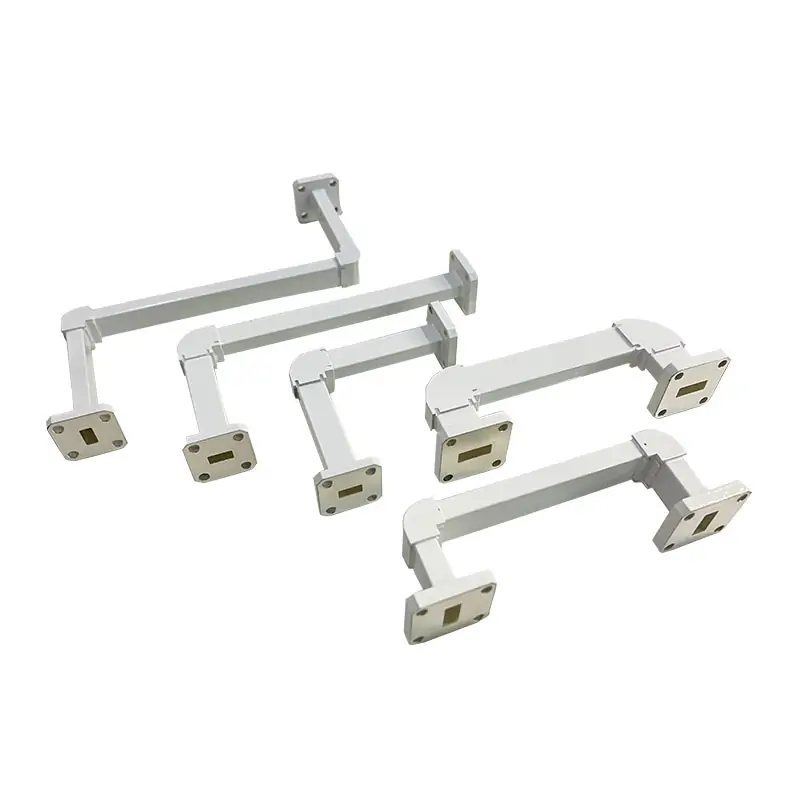
Waveguide miter bends are precision-engineered components used to change the direction of microwave signals within a waveguide system. They are designed for minimal signal loss and reflection, ensuring efficient signal transmission. These bends are critical in complex microwave systems, radar, satellite communications, and testing setups, accommodating various angles to meet specific design requirements.
Dolph Microwave · Rectangular waveguide
Need a waveguide run to turn a corner? Start with your WR size and the direction of the bend. The model table gives you the flange options, standard A×B dimensions and RF figures for each version.
Dolph Microwave product image from this page’s gallery when available; otherwise an illustrative drawing.
Check it in the full model table below. Keep the E/H suffix when you enquire.
Send a photo or drawing of both flange faces and the available space around the corner.
Include the bend angle, A×B dimensions and any flange or finish changes.
Bend orientation
E-plane and H-plane models can have the same WR size and frequency range, but their published bandwidth and standard leg dimensions differ.
Look for WTEB in the model code. The published E-plane rows list Full BW. Match the A×B size to the planned bend in your drawing.
The sketch illustrates the bend type, not flange geometry or part dimensions.
Look for WTHB in the model table. These rows list 20% operating bandwidth. Their standard A×B dimensions often differ from the E-plane version.
The sketch illustrates the bend type, not flange geometry or part dimensions.
Unsure which one matches your run? Share a photo or drawing showing the waveguide’s broad face and the direction of the turn. For another routing option, see waveguide twists when the orientation must rotate rather than the path simply turning.
Mechanical fit
Two bends with the same WR size can take up different amounts of space. Use the A×B entry in the exact E-plane or H-plane row, then check both ends against the equipment you are joining.
The older manufacturer’s PDF also labels Flange 1, Flange 2, A and B, but some of its dimensions differ from the current online table. Open the original miter-bend PDF.
Flange interfaces
The model table lists a cover and a grooved flange designation for every row. Do not pick a flange only because its waveguide size looks right: the aperture, bolt pattern and sealing face need to match the equipment on each side.
6061 aluminum is stated in the product features. Copper and brass are also described as options.
Each published row lists Al/Cu. State the required body material in the enquiry.
Chromate/Painted is listed in the table. The page separately mentions grey paint and flat black; confirm the selected finish.
Complete catalog matrix
All 48 models are shown below. The figures and designations are kept as published, rather than combined into a general rating.
On smaller screens, swipe the table sideways. Use the model suffix to keep the E-plane and H-plane versions separate. “Full BW” and “20%” are the original operating-bandwidth labels.
| Model / plane | Freq. range GHz | Operating BW | WG size | VSWR | IL dB | Cover flange | Grooved flange | Std. size A×B mm | Material | Finish | Datasheet labels |
|---|---|---|---|---|---|---|---|---|---|---|---|
| E-PLANEDH-3WTEBA*B…. | 0.32-0.49 | Full BW | WR2300 | 1.15:1 | 0.15 | UDR3 | PDR3 | 220*220 | Al/Cu | Chromate/Painted | PDFSTEP |
| H-PLANEDH-3WTHBA*B…. | 0.32-0.49 | 20% | WR2300 | 1.15:1 | 0.15 | UDR3 | PDR3 | 350*650 | Al/Cu | Chromate/Painted | PDFSTEP |
| E-PLANEDH-4WTEBA*B…. | 0.35-0.53 | Full BW | WR2100 | 1.15:1 | 0.15 | UDR4 | PDR4 | 200*200 | Al/Cu | Chromate/Painted | PDFSTEP |
| H-PLANEDH-4WTHBA*B…. | 0.35-0.53 | 20% | WR2100 | 1.15:1 | 0.15 | UDR4 | PDR4 | 330*330 | Al/Cu | Chromate/Painted | PDFSTEP |
| E-PLANEDH-5WTEBA*B…. | 0.41-0.62 | Full BW | WR1800 | 1.1:1 | 0.15 | UDR5 | PDR5 | 180*180 | Al/Cu | Chromate/Painted | PDFSTEP |
| H-PLANEDH-5WTHBA*B…. | 0.41-0.62 | 20% | WR1800 | 1.1:1 | 0.15 | UDR5 | PDR5 | 300*300 | Al/Cu | Chromate/Painted | PDFSTEP |
| E-PLANEDH-6WTEBA*B…. | 0.49-0.75 | Full BW | WR1500 | 1.1:1 | 0.15 | UDR6 | PDR6 | 150*150 | Al/Cu | Chromate/Painted | PDFSTEP |
| H-PLANEDH-6WTHBA*B…. | 0.49-0.75 | 20% | WR1500 | 1.1:1 | 0.15 | UDR6 | PDR6 | 240*240 | Al/Cu | Chromate/Painted | PDFSTEP |
| E-PLANEDH-8WTEBA*B…. | 0.64-0.98 | Full BW | WR1150 | 1.1:1 | 0.15 | UDR8 | PDR8 | 130*130 | Al/Cu | Chromate/Painted | PDFSTEP |
| H-PLANEDH-8WTHBA*B…. | 0.64-0.98 | 20% | WR1150 | 1.1:1 | 0.15 | UDR8 | PDR8 | 220*220 | Al/Cu | Chromate/Painted | PDFSTEP |
| E-PLANEDH-9WTEBA*B…. | 0.75-1.15 | Full BW | WR975 | 1.1:1 | 0.15 | UDR9 | PDR9 | 120*120 | Al/Cu | Chromate/Painted | PDFSTEP |
| H-PLANEDH-9WTHBA*B…. | 0.75-1.15 | 20% | WR975 | 1.1:1 | 0.15 | UDR9 | PDR9 | 200*200 | Al/Cu | Chromate/Painted | PDFSTEP |
| E-PLANEDH-12WTEBA*B…. | 0.96-1.46 | Full BW | WR770 | 1.1:1 | 0.15 | UDR12 | PDR12 | 110*110 | Al/Cu | Chromate/Painted | PDFSTEP |
| H-PLANEDH-12WTHBA*B…. | 0.96-1.46 | 20% | WR770 | 1.1:1 | 0.15 | UDR12 | PDR12 | 160*160 | Al/Cu | Chromate/Painted | PDFSTEP |
| E-PLANEDH-14WTEBA*B…. | 1.13-1.73 | Full BW | WR650 | 1.1:1 | 0.15 | UDR14 | PDR14 | 100*100 | Al/Cu | Chromate/Painted | PDFSTEP |
| H-PLANEDH-14WTHBA*B…. | 1.13-1.73 | 20% | WR650 | 1.1:1 | 0.15 | UDR14 | PDR14 | 140*140 | Al/Cu | Chromate/Painted | PDFSTEP |
| E-PLANEDH-18WTEBA*B…. | 1.45-2.20 | Full BW | WR510 | 1.1:1 | 0.15 | UDR18 | PDR18 | 90*90 | Al/Cu | Chromate/Painted | PDFSTEP |
| H-PLANEDH-18WTHBA*B…. | 1.45-2.20 | 20% | WR510 | 1.1:1 | 0.15 | UDR18 | PDR18 | 120*120 | Al/Cu | Chromate/Painted | PDFSTEP |
| E-PLANEDH-22WTEBA*B…. | 1.72-2.61 | Full BW | WR430 | 1.1:1 | 0.15 | UDR22 | PDR22 | 70*70 | Al/Cu | Chromate/Painted | PDFSTEP |
| H-PLANEDH-22WTHBA*B…. | 1.72-2.61 | 20% | WR430 | 1.1:1 | 0.15 | UDR22 | PDR22 | 100*100 | Al/Cu | Chromate/Painted | PDFSTEP |
| E-PLANEDH-26WTEBA*B…. | 2.17-3.30 | Full BW | WR340 | 1.1:1 | 0.2 | UDR26 | PDR26 | 70*70 | Al/Cu | Chromate/Painted | PDFSTEP |
| H-PLANEDH-26WTHBA*B…. | 2.17-3.30 | 20% | WR340 | 1.1:1 | 0.2 | UDR26 | PDR26 | 100*100 | Al/Cu | Chromate/Painted | PDFSTEP |
| E-PLANEDH-32WTEBA*B…. | 2.60-3.95 | Full BW | WR284 | 1.1:1 | 0.2 | UDR32 | PDR32 | 60*60 | Al/Cu | Chromate/Painted | PDFSTEP |
| H-PLANEDH-32WTHBA*B…. | 2.60-3.95 | 20% | WR284 | 1.1:1 | 0.2 | UDR32 | PDR32 | 65*65 | Al/Cu | Chromate/Painted | PDFSTEP |
| E-PLANEDH-40WTEBA*B…. | 3.22-4.90 | Full BW | WR229 | 1.1:1 | 0.2 | UDR40 | PDR40 | 45*45 | Al/Cu | Chromate/Painted | PDFSTEP |
| H-PLANEDH-40WTHBA*B…. | 3.22-4.90 | 20% | WR229 | 1.1:1 | 0.2 | UDR40 | PDR40 | 60*60 | Al/Cu | Chromate/Painted | PDFSTEP |
| E-PLANEDH-48WTEBA*B…. | 3.94-5.99 | Full BW | WR187 | 1.1:1 | 0.2 | UDR48 | PDR348 | 45*45 | Al/Cu | Chromate/Painted | PDFSTEP |
| H-PLANEDH-48WTHBA*B…. | 3.94-5.99 | 20% | WR187 | 1.1:1 | 0.2 | UDR48 | PDR348 | 60*60 | Al/Cu | Chromate/Painted | PDFSTEP |
| E-PLANEDH-58WTEBA*B…. | 4.64-7.05 | Full BW | WR159 | 1.1:1 | 0.2 | UDR58 | PDR58 | 40*40 | Al/Cu | Chromate/Painted | PDFSTEP |
| H-PLANEDH-58WTHBA*B…. | 4.64-7.05 | 20% | WR159 | 1.1:1 | 0.2 | UDR58 | PDR58 | 50*50 | Al/Cu | Chromate/Painted | PDFSTEP |
| E-PLANEDH-70WTEBA*B…. | 5.38-8.17 | Full BW | WR137 | 1.1:1 | 0.2 | UDR70 | PDR70 | 35*35 | Al/Cu | Chromate/Painted | PDFSTEP |
| H-PLANEDH-70WTHBA*B…. | 5.38-8.17 | 20% | WR137 | 1.1:1 | 0.2 | UDR70 | PDR70 | 45*45 | Al/Cu | Chromate/Painted | PDFSTEP |
| E-PLANEDH-84WTEBA*B…. | 6.57-9.99 | Full BW | WR112 | 1.1:1 | 0.2 | UDR84/UBR84 | PDR84/PBR84 | 30*30 | Al/Cu | Chromate/Painted | PDFSTEP |
| H-PLANEDH-84WTHBA*B…. | 6.57-9.99 | 20% | WR112 | 1.1:1 | 0.2 | UDR84/UBR84 | PDR84/PBR84 | 40*40 | Al/Cu | Chromate/Painted | PDFSTEP |
| E-PLANEDH-100WTEBA*B…. | 8.20-12.40 | Full BW | WR90 | 1.1:1 | 0.2 | UDR100/UBR100 | PDR100/PBR100 | 25*25 | Al/Cu | Chromate/Painted | PDFSTEP |
| H-PLANEDH-100WTHBA*B…. | 8.20-12.4 | 20% | WR90 | 1.1:1 | 0.2 | UDR100/UBR100 | PDR100/PBR100 | 30*30 | Al/Cu | Chromate/Painted | PDFSTEP |
| E-PLANEDH-120WTEBA*B…. | 9.84-15.0 | Full BW | WR75 | 1.1:1 | 0.25 | UBR120 | PBR120 | 25*25 | Al/Cu | Chromate/Painted | PDFSTEP |
| H-PLANEDH-120WTHBA*B…. | 9.84-15.0 | 20% | WR75 | 1.1:1 | 0.25 | UBR120 | PBR120 | 30*30 | Al/Cu | Chromate/Painted | PDFSTEP |
| E-PLANEDH-140WTEBA*B…. | 11.9-18.0 | Full BW | WR62 | 1.1:1 | 0.25 | UBR140 | PBR140 | 20*20 | Al/Cu | Chromate/Painted | PDFSTEP |
| H-PLANEDH-140WTHBA*B…. | 11.9-18.0 | 20% | WR62 | 1.1:1 | 0.25 | UBR140 | PBR140 | 25*25 | Al/Cu | Chromate/Painted | PDFSTEP |
| E-PLANEDH-180WTEBA*B…. | 14.5-22.0 | Full BW | WR51 | 1.1:1 | 0.25 | UBR180 | PBR180 | 20*20 | Al/Cu | Chromate/Painted | PDFSTEP |
| H-PLANEDH-180WTHBA*B…. | 14.5-22.0 | 20% | WR51 | 1.1:1 | 0.25 | UBR180 | PBR180 | 25*25 | Al/Cu | Chromate/Painted | PDFSTEP |
| E-PLANEDH-220WTEBA*B…. | 17.6-26.7 | Full BW | WR42 | 1.1:1 | 0.25 | UBR220 | PBR220 | 15*15 | Al/Cu | Chromate/Painted | PDFSTEP |
| H-PLANEDH-220WTHBA*B…. | 17.6-26.7 | 20% | WR42 | 1.1:1 | 0.25 | UBR220 | PBR220 | 20*20 | Al/Cu | Chromate/Painted | PDFSTEP |
| E-PLANEDH-260WTEBA*B…. | 21.7-33.0 | Full BW | WR34 | 1.1:1 | 0.25 | UBR260 | PBR260 | 15*15 | Al/Cu | Chromate/Painted | PDFSTEP |
| H-PLANEDH-260WTHBA*B…. | 21.7-33.0 | 20% | WR34 | 1.1:1 | 0.25 | UBR260 | PBR260 | 20*20 | Al/Cu | Chromate/Painted | PDFSTEP |
| E-PLANEDH-320WTEBA*B…. | 26.5-40.0 | Full BW | WR28 | 1.1:1 | 0.25 | UBR320 | PBR320 | 12*12 | Al/Cu | Chromate/Painted | PDFSTEP |
| H-PLANEDH-320WTHBA*B…. | 26.5-40.0 | 20% | WR28 | 1.1:1 | 0.25 | UBR320 | PBR320 | 18*18 | Al/Cu | Chromate/Painted | PDFSTEP |
Check the right revision.The archived PDF lists a narrower range and some different A×B sizes. Use the current model row as a starting point and request the selected model’s latest drawing before manufacture.
PDF and STEP labels.The original table shows PDF and STEP for each model. Individual file addresses are not exposed by the source, so these labels are retained without pretending they are downloadable files. Request the files for your part number. The WR187 rows also print “PDR348” as the grooved flange code; confirm this designation against the latest drawing before ordering.
Published electrical data
The page also contains a general VSWR statement and an older specification example. Those are not substitutes for the model-by-model figures.
1.15:1 for the DH-3 and DH-4 E/H models; 1.1:1 for the remaining published rows.
0.15 dB, 0.2 dB or 0.25 dB, depending on the selected model. Check its exact value above.
It states VSWR “typically better than 1.05” and “as low as 1.03:1 over a 5% bandwidth.” It does not assign these values to all models.
The manufacturer also publishes this example. It is reproduced here for completeness, but its frequency range conflicts with the DH-100 rows in the current catalog.
| Type | DH-100 WTEB |
|---|---|
| Frequency Range | 0.32 to 3.3 GHz |
| Max VSWR | 1.1:1 |
| Operating Bandwidth | 20% |
| Waveguide Sizes | WR-340 to WR-2300 |
| Material | Aluminum, Copper |
| Finishes | Chromate inside, Grey paint outside |
| Flange Type | UG, CPR, Custom |
Important: the current DH-100WTEB row states 8.20–12.40 GHz, and DH-100WTHB states 8.20–12.4 GHz. Please check the model-specific datasheet before using the older example in a design.
Ordering code
This is the manufacturer’s published ordering example. It identifies the WR size, bend type, A×B dimensions, flange configuration and material.
DH-100WTEB25*25PMA
If a part is being replaced, send the existing full code and a photo or drawing of the flange ends. A WR number alone does not identify the complete bend.
Check the quote detailsDolph Microwave prefix in the example.
Waveguide Size | WR90
Waveguide Type | Miter E-Bend Waveguide
Waveguide Type | Miter H-Bend Waveguide, as printed in the original part-number guide.
A*B Length | 25*25 mm
Flange Type | Rectangular Flat
Flange Type | Rectangular Grooved
Material | Aluminium, Cu
Code check: the ordering guide says “WHB” for H-bend, but the H-plane entries in the current model table use “WTHB.” State the full model and confirm the H-plane code before ordering.
Where these bends are used
Use the bend plane and the actual installation drawing to select the part, rather than choosing from an application name alone.
Build options and surface finish
The product features specify 6061 aluminum for standard use, with copper and brass options. The model matrix gives Al/Cu and Chromate/Painted for every entry.
The page mentions chromate conversion inside and grey corrosion-resistant paint outside. Its additional note separately states SurTec/corrosion-protection treatment, flat-black paint and unplated, polished, SurTec-treated flanges. Other finishes and colors are described as available on request.
Grey and flat black are both mentioned in the original copy. State the required internal treatment, outer color and flange finish in your order documentation instead of assuming one universal finish.
Preformed bends and hybrid flexible waveguide assemblies are also mentioned as available. See flexible waveguide options or send your installation sketch for a non-standard assembly review.
Questions before you order
The product describes 90° as standard and lists 30°, 45° and 60° as special-order angles. Include the desired angle and leg dimensions with your drawing.
No. Both types have their own rows. The source lists Full BW for E-plane entries and 20% for H-plane entries, with different A×B sizes in many cases.
Not necessarily. Tell the manufacturer the flange required on each end, with the mating part or flange drawing where possible. Use the specific cover/grooved designation in the chosen row as your reference.
PDF and STEP are shown for every row on the source page, but the public model-table file URLs could not be verified. Ask for the exact part number’s current STEP file and PDF drawing.
The published miter-bend model table does not list a per-model power rating. Provide average/peak power and operating conditions if this matters for your system, and request confirmation for the selected build.
Send the usable space, required angle, WR size, both flange types and a sketch. The manufacturer describes special sizes, flange options and E/H combinations for review.
Drawings and reference material
Original manufacturer PDF with E-bend and H-bend drawings and historical model information. Some A×B values and the covered range differ from the live table.
Download the original PDFCheck the published flange designations and mating details before the final drawing is approved.
Flange standard EIA & IECFlange size and gasket guideFor more detail about custom mechanical interfaces, see common mistakes in custom waveguide assemblies. Individual model PDF and STEP links are not substituted with the general PDF.
Build the complete waveguide run
The right add-on depends on whether the next section needs a straight connection, a twist, a flexible joint or a mating seal.
Connect two matching waveguide interfaces across a fixed straight length.
View product ↗Use when you need to change the waveguide orientation as well as plan the route.
View product ↗Review options for installations that cannot use a fully rigid run.
View product ↗Check the sealing part against the exact flange and operating conditions.
View product ↗Images for related products load from each linked Dolph Microwave product page when available; schematic illustrations are used as labelled fallbacks.
For a model check and quotation
A model number or drawing is a good start. Add the items below where they are known so the correct bend and flange pair can be checked before pricing.
Full frequency range, waveguide designation, and RF targets if your project has them.
E-plane or H-plane, 90° or special angle, required legs and available installation space.
Cover or grooved designation on each end, orientation and mating-part details.
Aluminum, copper or other requested material; inside, outside and flange treatment.
Part number, current drawing, revision or replacement photo; request the matching PDF / STEP if needed.
Required quantity and target date; include power, environment or sealing needs where relevant.
Use the existing product-page enquiry control, or send the specification and drawing to [email protected]. Pricing, delivery and model-specific acceptance requirements should be confirmed in the quotation.
Dolph Microwave warrants our products to be free from defective material and workmanship for a period of one year from the date of delivery. All defective parts will be replaced and repair work required by normal use will be performed, without charge, within this one year period. This warranty shall be exclusive and in lieu of all other warranties expressed or implied.



FengHuiNan Road NO.34, High-Tech Zone, Xi an, China
Tel/Fax: (+86) 29-8881-0979
E-mail: Sales@dolphmicrowave.com







