
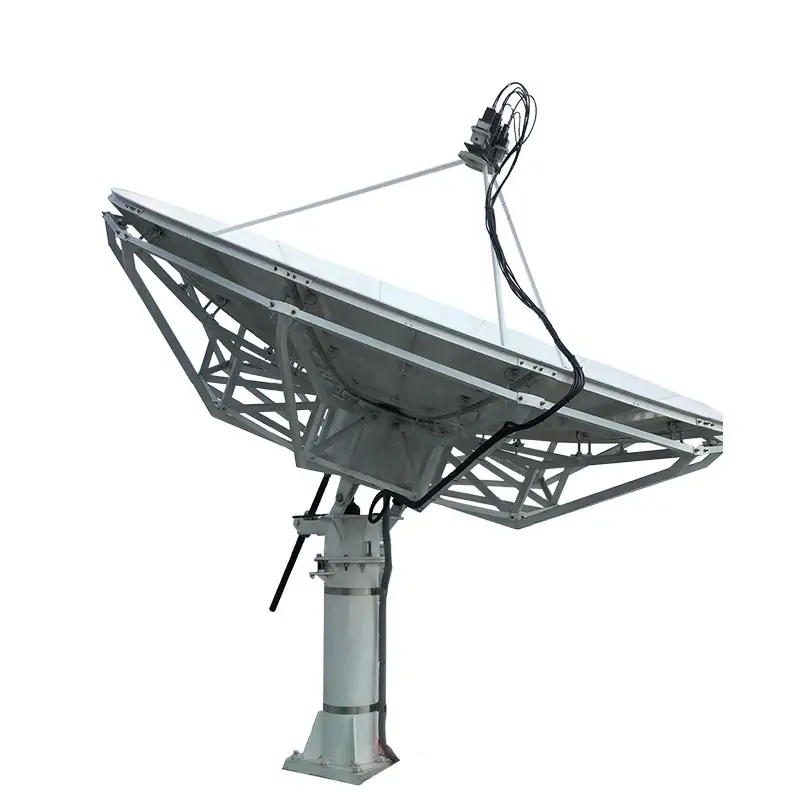
3.7 & 4.5 Meter Prime-Focus Antenna Systems
Published 3.7 m and 4.5 m prime-focus configurations include model-specific C- and Ku-band receive data, feed options and manual or motorized operation. Send site, mounting and feed requirements for configuration review.
Choose the System Around the Site
4.5 Meters (14.7Feet)
Published Configuration
| Parameter | 3.7 Meter Specifications | 4.5 Meter Specifications |
|---|---|---|
| Frequency Bands | L, X, Ku | L, X, Ku |
| Reflector Material | Aluminum Draw Die Formed | Aluminum Draw Die Formed |
| Construction | Galvanized Steel | Galvanized Steel |
| Wind Survival | 125 mph (200 km/h) published standard; any 180 mph configuration must be confirmed in the quotation | 125 mph (200 km/h) published standard; any 180 mph configuration must be confirmed in the quotation |
| Mounting Options | Non-Penetrating, Penetrating | Non-Penetrating, Penetrating |
| Feed System | Single Feed, Multi-Feed Available | Single Feed, Multi-Feed Available |
| Operation | Manual, Motorized | Manual, Motorized |
The downloadable 3.7 m and 4.5 m sheets publish a survival-wind value of 125 mph (200 km/h) and model-specific C/Ku receive data. Any 180 mph high-wind configuration is quotation-only and must be confirmed for the selected model, mount and site conditions.
Product Features From the Specification Sheets
Published C/Ku Receive Performance
Values below follow the original 3.7 m and 4.5 m specification sheets.
DH 3.7 Meter PF C/ Ku-band Antenna
| C/Ku-band Linear | Receive | Receive |
| Frequency, GHz | 3.625-4.2 | 10.95-12.75 |
| VSWR | 1.4:1 | 1.3:1 |
| 3dBBeam Width, deg | 1.45 | 0.44 |
| Noise Temperature 20 Deg Elevation, K | 36 | 37 |
| 30 Deg Elevation, K | 33 | 34 |
| Port to Port Isolation Rx to Rx (same band),dB | 30 | 30 |
| Axial ratio,dB | 1.5 | |
| Cross-pol on Axis, dB | 30 | 30 |
| Insertion Loss, dB | 0.35 | 0.25 |
| Feed Interface | WR-229 CPR | WR-75 CPR |
| Radiation Pattern Compliance | FCC 25.209, ITU-RS.580-6, | |
| First sidelobe, dB | ≤ -14 | |
| Sidelobe Envelope | 32 – 25 log (1°≤θ<20°) | |
DH 4.5 Meter PF C/ Ku-band Antenna
| C/Ku-band Linear | Receive | Receive |
| Frequency, GHz | 3.625-4.2 | 10.95-12.75 |
| VSWR | 1.4:1 | 1.3:1 |
| 3dBBeam Width, deg | 1.14 | 0.36 |
| Noise Temperature 20 Deg Elevation, K | 43 | 48 |
| 30 Deg Elevation, K | 40 | 43 |
| Port to Port Isolation Rx to Rx (same band),dB | 30 | 30 |
| Axial ratio,dB | 1.5 | |
| Cross-pol on Axis, dB | 30 | 30 |
| Insertion Loss, dB | 0.35 | 0.25 |
| Feed Interface | WR-229 CPR | WR-75 CPR |
| Radiation Pattern Compliance | FCC 25.209, ITU-RS.580-6, | |
| First sidelobe, dB | ≤ -14 | |
| Sidelobe Envelope | 32 – 25 log (1°≤θ<20°) | |
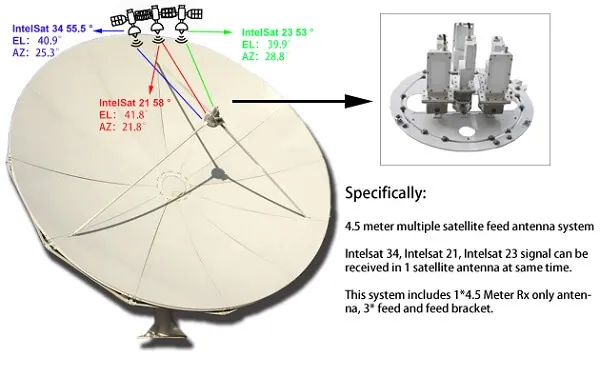
Feed and Multi-Beam Options
The product specification lists C/Ku dual-band feed systems and MultiBeam satellite dish solutions. A published 4.5 m prime-focus multi-beam configuration shows simultaneous reception of adjacent satellites with dedicated feed support hardware.
For a custom feed, send the band, polarization, reflector F/D and required interface. Dolph also publishes complete custom antenna feed systems and a 4.5 m multi-beam feed reference.
Ask About Feed ConfigurationMechanical Specifications
3.7 Meter Prime Focus Antenna System
| Antenna Optics | Prime focus design |
| Reflector Aperture | 3.7 Meters (12Feet) |
| Reflector Panels | 12 precision-formed aluminum panels |
| F/D Ratio | 0.365 |
| Mount Configuration | Turning Head Pedestal Elevation-over Azimuth axis configuration |
| Drive Type | Manual / Motorized jack screw |
| Surface Accuracy (RMS) | 0.5 mm |
| Elevation Travel | 0° to 90 ° Continuous, Including El Angle Adjustment Mark, |
| Azimuth Travel | ±85° or 360°Continuous, |
| Pol. Travel | ±90°Continuous, |
| Antenna Foundation | Reinforced Concrete Foundation, or Non-penetrating mount (NPM) |
| Shiping Case | 3 Case, Seaworthy Packing |
| Shipping Weight | 600KG, Total volume: 4.11CBM |
4.5 Meter Prime Focus Antenna System
| Antenna Optics | Prime focus design |
| Reflector Aperture | 4.5 Meters (14.7Feet) |
| Reflector Panels | 12 precision-formed aluminum panels |
| F/D Ratio | 0.4 |
| Mount Configuration | Turning Head Pedestal Elevation-over Azimuth axis configuration |
| Drive Type | Manual / Motorized jack screw |
| Surface Accuracy (RMS) | 0.5 mm |
| Elevation Travel | 0° to 90 ° Continuous, Including El Angle Adjustment Mark, |
| Azimuth Travel | ±85° or 360°Continuous, |
| Pol. Travel | ±90°Continuous, |
| Antenna Foundation | Reinforced Concrete Foundation, or Non-penetrating mount (NPM) |
| Shiping Case | 3 Case, Seaworthy Packing |
| Shipping Weight | 839KG, Total volume: 5.14CBM |
Environmental Performance and Packing
| Operational Wind | 45 mph (72 km/h) gusting to 60 mph (97 km/h) |
| Survival Wind | 125 mph (200 km/h), |
| Temperature | -40° C to +50° C |
| Humidity | 0-98% |
600KG, Total volume: 4.11CBM
839KG, Total volume: 5.14CBM
Application Fit
Fixed satellite signal reception for broadcast sites.
Receive infrastructure for satellite-supported networks.
Satellite data reception for research sites.
Fixed receive infrastructure for supported emergency-site communication systems.
Satellite reception for remote fixed locations.
What to Send for Quotation
A useful RFQ lets the antenna, feed and mounting configuration be checked together before production.
If This Aperture or Architecture Is Not the Right Fit
Compare the 2.4/3.0 Meter Rx only Antenna Systems.
Review the 6.0 Meter Receive Only Antenna.
Compare the 3.7/4.5 Meter Dual-Reflector Earth Station Antennas System.







