
+86 29 8881 0979

3.7 Meter Transportable Trailer Mounted Antenna

A 3.7-meter transportable trailer-mounted antenna is a mobile communication solution designed for rapid deployment and high-performance signal transmission. It offers flexibility and reliability for field operations, satellite communications, and emergency response scenarios, ensuring robust connectivity in various environments.

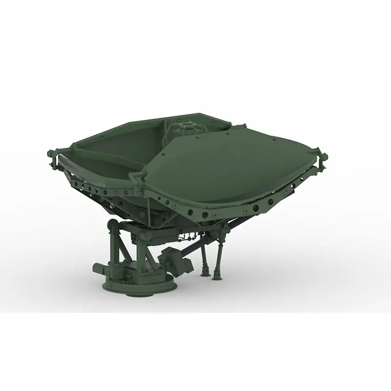
The 3.7 Meter Transportable Trailer-Mounted SATCOM Antenna is designed for temporary satellite communication sites that require a larger reflector to be relocated between operating locations. The published product image shows the multi-section reflector in its stowed configuration. Operating band, receive or transmit function, polarization, feed network, pointing and control method, outdoor-unit interface, transport envelope and environmental limits are configured and confirmed for each project rather than assumed from the reflector diameter alone.


Transportable SATCOM Platform

A 3.7 m Reflector for Relocatable Satellite Communication Sites

This system is positioned between compact flyaway or roof-mounted terminals and permanently installed earth-station antennas. It provides a 3.7-meter reflector on a transportable trailer-mounted platform for projects that need to move the antenna between sites while retaining a larger aperture. The final RF and mechanical configuration is defined around the actual link, transport and operating requirements.


Published aperture: 3.7 meter

Platform: transportable trailer-mounted antenna

Shown condition: multi-section reflector in stowed position

Configuration: confirmed against project requirements

System Scope

What Must Be Engineered Around the 3.7 m Reflector

Reflector diameter is only one part of a transportable SATCOM terminal. A usable project configuration also requires the feed, RF path, pointing arrangement, outdoor-unit load, electrical interfaces, transport limits and site conditions to be defined together.


Reflector and Stow Geometry

Confirm deployed dimensions, stowed dimensions, panel deployment method, support structure, leveling arrangement and clearance around the antenna during operation.


Operating Band and Link Function

State the exact uplink and downlink frequency ranges, receive-only or transmit/receive function, satellite service and required RF performance targets.


Feed and Polarization

Define linear or circular polarization, single- or dual-polarized operation, port arrangement, feed interface and any required OMT, polarizer, filter or diplexer functions.


Transport and Chassis Interface

Provide towing, axle, road envelope, permitted mass, center-of-gravity, tie-down, braking, lighting and local registration constraints for the destination market.


Pointing and Control

Confirm manual, motorized or automatic acquisition requirements, axis travel, pointing resolution, position feedback, controller interface and any beacon or modem inputs.


Site and Environmental Limits

Define operating and survival wind conditions, temperature, humidity, rain, dust, altitude, terrain, deployment surface and available electrical power.

Technical Information

Published Data and Project-Confirmed Parameters

The current product record publishes the antenna diameter and transportable format but does not publish a model datasheet with RF, mechanical or environmental values. Those items should be confirmed in the quotation and approved specification.

Request project specification

Parameter Current Status Required Confirmation
Reflector aperture 3.7 meter Nominal aperture and reflector geometry on approved drawing
System format Transportable trailer-mounted antenna Trailer/chassis scope, tow interface and destination-road requirements
Reflector arrangement Product image shows a stowed multi-section structure Deployment method, panel count, deployed envelope and locking procedure
Frequency range Not published for this model Exact Rx and Tx ranges; do not specify only a general band name
Gain, G/T and EIRP Not published for this model Link-budget targets and reference frequencies
Polarization Not published for this model Linear/circular, handedness, dual-polarized or switchable requirement
Feed and RF interface Project specific Feedhorn, OMT/polarizer, filter/diplexer, waveguide size and flange
Pointing system Not published for this model Manual/motorized/auto-acquisition, axis travel and controller functions
Outdoor-unit integration Project specific BUC/HPA/LNB/LNA type, mass, power, cooling and cable routing
Wind and environment Not published for this model Operating/stowed limits, temperature, ingress and deployment-site conditions
Power and control Not published for this model Input voltage/frequency, peak load, interfaces and remote-control needs
Packing and shipping Project specific Shipping method, lifting points, dimensions, mass and destination constraints
Application Fit

Where a Transportable 3.7 m Antenna Can Be Considered

The system is intended for stationary operation after deployment. It should not be described as an antenna for communication while the trailer is moving unless a separately engineered on-the-move system is specified.

01

Temporary Broadcast or Contribution Site

A relocatable platform for event, news or field operations where the project-approved receive or transmit/receive package supports the required satellite link.

02

Emergency Communication Hub

A deployable satellite terminal for restoring or supplementing communications at a temporary response location.

03

Remote Field Network

Temporary voice, video or data backhaul for remote operations when terrestrial links are unavailable or insufficient.

04

Relocatable Test or Monitoring Site

Projects that need a reflector-based terminal to operate at multiple fixed locations over the equipment life cycle.

Product Selection

Choose by Deployment Model, Not Diameter Alone

A transportable trailer platform, roof-mounted driveaway antenna, flyaway kit and fixed earth station solve different logistics problems. Compare the deployment method first, then confirm aperture, band and link requirements.

System Type Best Fit Key Constraint to Check Related Product
3.7 m transportable trailer-mounted Relocation between temporary operating sites with a larger reflector Road envelope, site leveling, deployment clearance and project-specific RF configuration Current system →
Vehicle roof-mounted driveaway Faster vehicle-based relocation with smaller published aperture options Roof load, stowed height, vehicle interface and axis/control configuration 1.2/1.5/1.8/2.4 m driveaway →
Quick-deploy flyaway Transport in cases and assembly away from a dedicated vehicle or trailer Packed mass, case size, assembly method and allowable setup time 1.8/2.4 m quick deploy →
Fixed prime-focus earth station Permanent or long-term site where transportability is not required Foundation/mount, installation access, wind design and long-term alignment 3.7/4.5 m prime focus →
Fixed dual-reflector earth station Permanent station requiring a dual-reflector antenna architecture Feed architecture, pedestal, installation and approved RF specification 3.7/4.5 m dual reflector →
Project Workflow

From Requirement Review to Approved Configuration

A transportable antenna should be quoted against a controlled requirement set. This prevents a mismatch between the RF link, feed system, outdoor units, pointing controls and trailer constraints.

View research, design and measurement support

01

Requirement Capture

Collect frequency ranges, link targets, satellite information, polarization, ODU details, transport limits, site conditions and required documents.

02

RF and Feed Definition

Define reflector-feed matching, polarization paths, component interfaces, filters/diplexers and transmit/receive equipment integration.

03

Mechanical and Control Review

Confirm stow/deploy geometry, leveling and stabilization, axis movement, controller requirements, power and cable routing.

04

Quotation and Specification Approval

Agree the supply boundary, drawings, datasheet values, accessories, test scope, packing, delivery terms and exclusions before order.

05

Integration and Verification

Apply the agreed inspection and measurement plan to the supplied antenna, feed system and associated microwave components.

Company Capability

Microwave Manufacturing and Measurement Support

Dolph’s established scope covers microwave components and antenna feed systems. The applicable production and verification steps for a trailer-mounted antenna project must be listed in the approved contract rather than assumed to apply automatically.


Manufacturing Processes

Published capabilities include CNC machining, turning, waveguide forming and bending, plating, soldering and brazing, anodising/passivation, grinding and electroforming.

View manufacturing capability →


Measurement Resources

Dolph lists RF vector and scalar systems up to 100 GHz, antenna anechoic chambers, high-power transmitters, waveguide calibration, EMI/EMS and environmental test capabilities.

View support and testing →


Quality Documentation

Dolph publishes an ISO 9001:2015 certificate whose stated scope is waveguide component design, manufacture and sale. It should not be presented as a product certificate for the complete antenna system.

View published certificate →

Warranty: Dolph’s published terms state a one-year warranty against defects in materials and workmanship under normal use and service, subject to the complete warranty conditions and exclusions.

Read terms and conditions →


Enquiry Checklist

Information Needed for a Meaningful Quotation

A complete requirement package reduces follow-up questions and helps separate mandatory performance from optional features.

1

Satellite and service: satellite name/orbital position, teleport or field service, planned carrier and modem.

2

Frequency: exact receive and transmit ranges, channel bandwidth and required waveguide band.

3

RF targets: gain/G/T/EIRP, VSWR, isolation, cross-polarization and radiation-pattern requirements.

4

Feed path: polarization, ports, OMT/polarizer, filters/diplexer, flange and interface drawings.

5

Outdoor units: BUC/HPA/LNB/LNA models, dimensions, mass, power, cooling and mounting requirements.

6

Pointing: manual, motorized or automatic acquisition; tracking need; control and telemetry interface.

7

Transport: destination country, road limits, towing vehicle, maximum stowed envelope and mass.

8

Environment: wind, temperature, rain/dust, altitude, terrain and deployment surface.

9

Power: supply voltage/frequency, generator or mains source, connector and grounding requirements.

10

Deliverables: drawings, manuals, test report, packing list, spares, training and acceptance requirements.

Technical Reading

Related Guides for Antenna and Feed Selection

These resources provide background for defining the antenna type, reflector size and feed-system architecture before submitting a project requirement.

FAQ

3.7 m Transportable Antenna Questions

Is this a 4.5 m vehicle-mounted antenna?+

The live product title and published product image identify a 3.7 Meter Transportable Trailer Mounted Antenna. The final quotation should use the approved product name and drawing rather than relying on the older URL wording.

Which frequency bands does this model support?+

The current product record does not publish a model-specific band or frequency range. Provide the exact receive and transmit ranges so the reflector-feed combination, interfaces and associated microwave components can be reviewed.

Does the antenna operate while the trailer is moving?+

This product is described as transportable and deployable for field operation. It should be treated as a stationary terminal after setup unless an approved specification explicitly includes communication on the move.

Are gain, wind speed and setup time available?+

Those values are not published on the current product record. They should be stated in the model datasheet or approved project specification after the feed, control, trailer and environmental configuration is fixed.

Can Dolph provide the feed and waveguide components?+

Dolph’s published scope includes microwave feedhorns, antenna feeder networks, OMTs, filters, diplexers, polarizers and waveguide components. The supplied items and performance values must be listed in the project quotation.

Is the complete antenna ISO certified?+

The published ISO 9001:2015 certificate states a scope covering waveguide component design, manufacture and sale. It is a quality-management-system certificate and should not be described as certification of the complete trailer-mounted antenna.

What documents should be approved before production?+

At minimum, approve the product specification, RF block diagram, interface-control information, deployed and stowed drawings, supply boundary, accessory list, test/acceptance scope, packing method and delivery documentation.





Define the Complete 3.7 m Transportable Antenna Configuration

Send the exact frequency ranges, link targets, polarization, feed interfaces, outdoor-unit details, pointing method, transport constraints and site conditions. Dolph can review the antenna and feed-system scope and return a project-specific technical proposal.

Discuss Your Antenna Requirement

Scroll to Top
Blank Form (#3)

