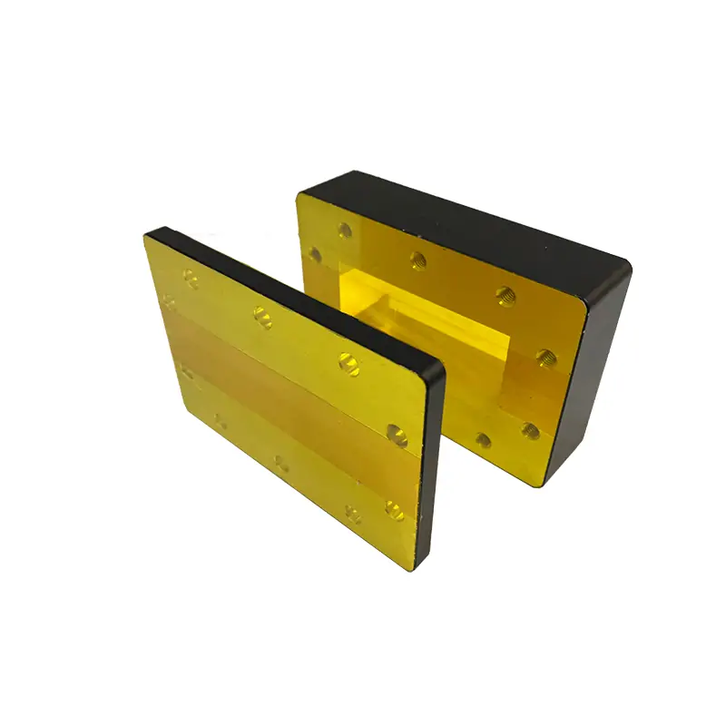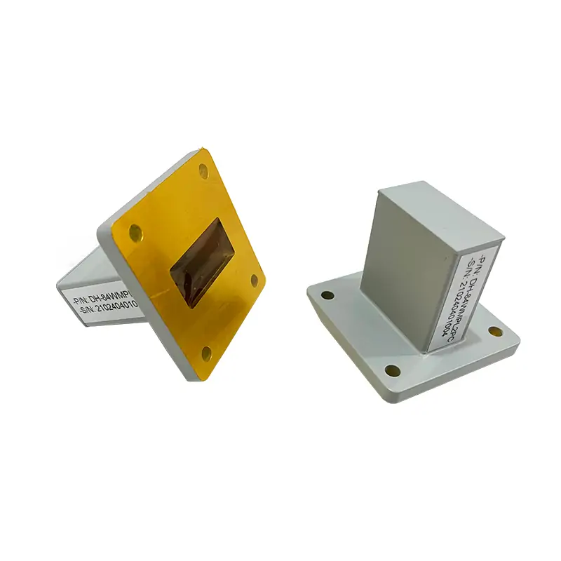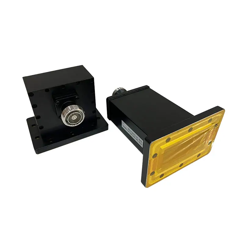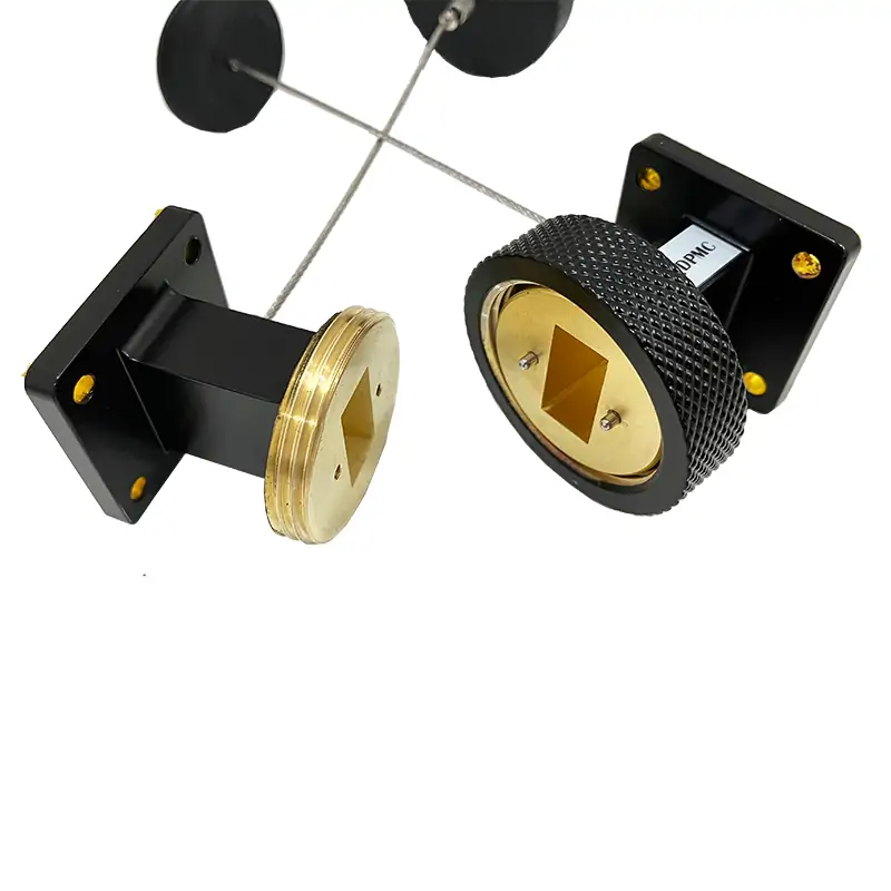
Double-Ridged Waveguide Quick Disconnect Assembly
A quick-disconnect for WRD waveguide lines that need to be opened and reconnected without working through a full set of conventional flange bolts. The published range covers WRD840 to WRD180, 0.84–40 GHz, 76 mm length, flat or grooved flange options, and model-specific VSWR from 1.15:1 to 1.2:1.
Use It When the Waveguide Section Needs to Come Off Again
This is not just a short piece of waveguide. The main reason to choose it is access. If a test section, field module or serviceable component has to be removed and put back, the thumb-screw quick-release arrangement can make that job simpler.
The part still has to match the actual mating waveguide. A WRD name by itself is not enough. The flat or grooved flange, ridge orientation, opening, alignment and available hand clearance around the locking point all matter.
What the Page Tells You — and What Still Needs Checking
Already published
- Model family and frequency range
- WRD waveguide size
- VSWR for each listed model
- 76 mm overall length
- Cover and grooved flange codes
- Al / Cu material options
- Chromate / Painted finish
- RoHS & REACH compliance status
Confirm for your order
- Exact mating flange drawing and orientation
- Available clearance around the thumb screw / clamp
- Required power level if it is a design limit
- Pressure or leakage requirement if the line is pressurized
- Repeated connection-cycle requirement if it matters to service life
- Any special finish, color or inspection documents
Start With Your Frequency Band, Then Match the Exact WRD Interface
The blocks below are only a fast way to find the right part of the table. Final selection should use the exact model row and flange code.
| MODEL | FREQ. RANGE (GHz) | WG SIZE | VSWR | LENGTH (mm) | FLANGES TYPE | MATERIAL | FINISH | ROHS & REACH | DATASHEET | |
|---|---|---|---|---|---|---|---|---|---|---|
| COVER | GROOVED | |||||||||
| DH-840DRWQDA… | 0.84-2.0 | WRD840 | 1.15:1 | 76 | FPWRD840U24 | FMWRD840U24 | Al/Cu | Chromate/Painted | Comply | DWG | STEP |
| DH-150DRWQDA… | 1.5-3.6 | WRD150 | 1.15:1 | 76 | FPWRD150D24 | FMWRD150D24 | Al/Cu | Chromate/Painted | Comply | DWG | STEP |
| DH-200DRWQDA… | 2.0-4.8 | WRD200 | 1.15:1 | 76 | FPWRD200D24 | FMWRD200D24 | Al/Cu | Chromate/Painted | Comply | DWG | STEP |
| DH-250DRWQDA… | 2.6-7.8 | WRD250 | 1.15:1 | 76 | FPWRD250D30 | FMWRD250D30 | Al/Cu | Chromate/Painted | Comply | DWG | STEP |
| DH-350DRWQDA… | 3.5-8.2 | WRD350 | 1.15:1 | 76 | FPWRD350D24 | FMWRD350D24 | Al/Cu | Chromate/Painted | Comply | DWG | STEP |
| DH-475DRWQDA… | 4.75-11.0 | WRD475 | 1.15:1 | 76 | FPWRD475D24 | FMWRD475D24 | Al/Cu | Chromate/Painted | Comply | DWG | STEP |
| DH-500DRWQDA… | 5.0-18.0 | WRD500 | 1.15:1 | 76 | FPWRD500D36 | FMWRD500D36 | Al/Cu | Chromate/Painted | Comply | DWG | STEP |
| DH-580DRWQDA… | 5.8-16.0 | WRD580 | 1.15:1 | 76 | FPWRD580D28 | FMWRD580D28 | Al/Cu | Chromate/Painted | Comply | DWG | STEP |
| DH-650DRWQDA… | 6.5-18.0 | WRD650 | 1.15:1 | 76 | FPWRD650D28 | FMWRD650D28 | Al/Cu | Chromate/Painted | Comply | DWG | STEP |
| DH-700DRWQDA… | 7.0-18.5 | WRD700 | 1.15:1 | 76 | FPWRD700D26 | FMWRD700D26 | Al/Cu | Chromate/Painted | Comply | DWG | STEP |
| DH-750DRWQDA… | 7.5-18.0 | WRD750 | 1.15:1 | 76 | FPWRD750D24 | FMWRD750D24 | Al/Cu | Chromate/Painted | Comply | DWG | STEP |
| DH-110DRWQDA… | 11.0-26.5 | WRD110 | 1.2:1 | 76 | FPWRD110C24 | FMWRD110C24 | Al/Cu | Chromate/Painted | Comply | DWG | STEP |
| DH-180DRWQDA… | 18.0-40.0 | WRD180 | 1.2:1 | 76 | FPWRD180C24 | FMWRD180C24 | Al/Cu | Chromate/Painted | Comply | DWG | STEP |
“WRD650” Is Not the Whole Interface
The waveguide size gets you into the right family. The actual joint still depends on the flange face. This page lists both cover and grooved codes, and those codes should be checked against the mating drawing before production.
If you do not know the flange name, send a clear front photo plus the main opening, outside dimensions, groove details and hole locations. That is more useful than guessing the code.
Useful reference
See the Flange Type Designations Information PDF before you put a flange code on the purchase specification.
Read the Part Number Before You Send the PO
"840DR"Waveguide Size | WRD840"WQDA"Waveguide Type | Quick Disconnect Assembly"76"Length | 76 mm"P"Flange Type | Rectangular Flat"M"Flange Type | Rectangular Grooved"A/C"Material | Aluminium, CuYou Do Not Need a Perfect Part Number to Start
A drawing is best, but a photo and the basic RF information are enough to begin the review. Send what you already know instead of waiting until every detail is complete.
Frequency
Your real minimum and maximum operating frequency.
Waveguide size
WRD size at the quick-disconnect joint.
Mating flange
Flange code, drawing or clear front photo with dimensions.
Space around the joint
Show nearby brackets, panels or other waveguide sections that can block the locking mechanism.
Power or pressure
State these if they matter to the design. They are not defined as universal ratings in the current quick-disconnect table.
Quantity & documents
Add quantity and tell us whether you need a drawing, STEP file, RF record or inspection document with the order.
When a Quick Disconnect Is Worth Using
It makes sense when
- A waveguide section is removed for service, test changes or equipment access.
- The joint is opened often enough that repeated conventional flange bolting is inconvenient.
- You already know the WRD size and can verify the mating flange.
- You want a defined 76 mm quick-disconnect section from the published range.
Check another solution when
- The line is permanent and is not expected to be opened after installation.
- You mainly need alignment or vibration movement — a flexible waveguide may be more relevant.
- You need to change from double-ridged to rectangular waveguide — use a waveguide transition.
- You need a defined pressure boundary — review the double-ridge pressure window.
Keep the Existing PDF Links With the Product
Flange Type Designations Information
Reference document for flange naming and waveguide interface designations.
High Power Termination
Existing PDF link currently attached to the live product page, retained here as requested.
Other Components Buyers Often Need Around This Joint
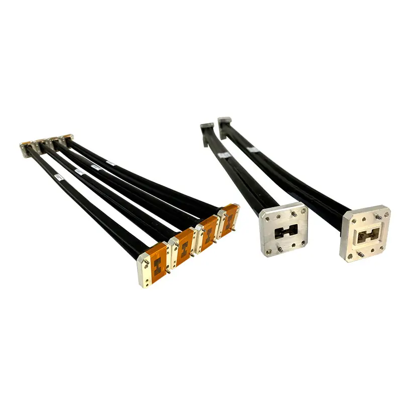
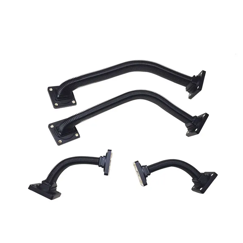
Flexible Waveguide
Useful when the main issue is routing, alignment or movement rather than fast disconnection.
View product →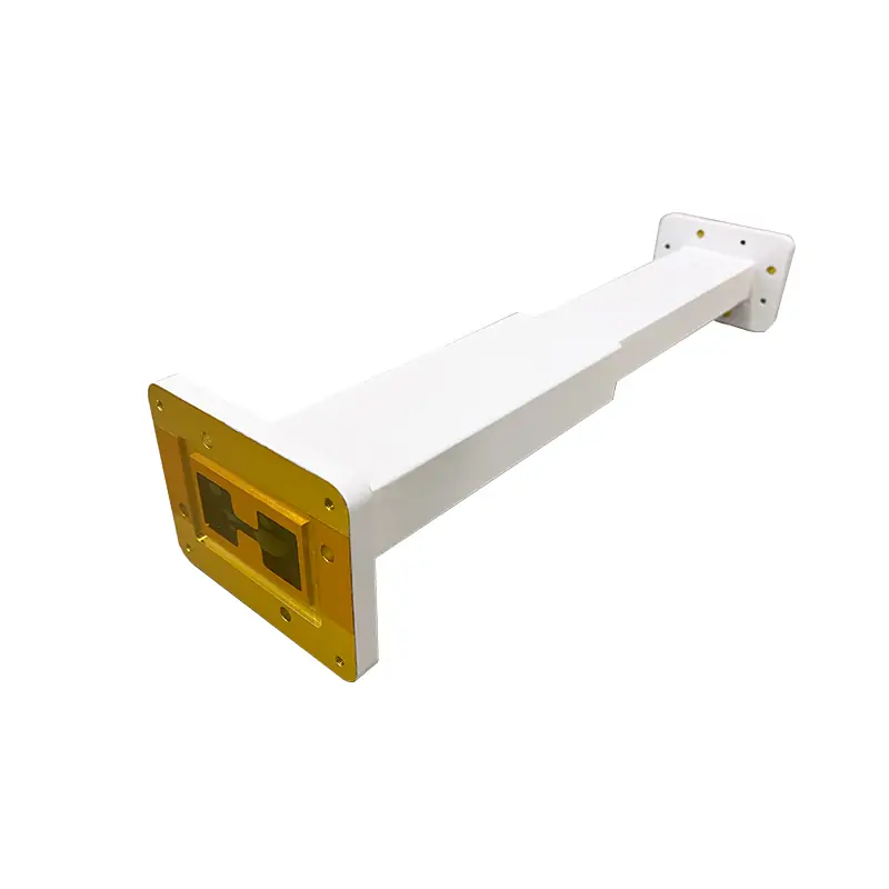
Rectangular Waveguide Transitions
For changing from a double-ridged interface to a standard rectangular waveguide interface.
View product →
Waveguide to Coaxial Adapter
For connecting the double-ridged waveguide path to a coaxial connector or RF instrument interface.
View product →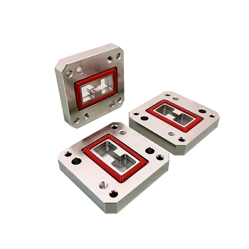
Double-Ridge Pressure Window
For systems that need a defined environmental or pressure barrier in the RF path.
View product →Useful Before You Freeze the Interface
Waveguide Compatibility, Fast Assembly & Signal Integrity
This guide explains why a quick-release joint still needs the full flange, alignment, RF and sealing details checked before approval. It is useful when you are replacing an existing connector or writing a new interface specification.
Read the selection guide →Custom Waveguide Assemblies
If the quick-disconnect is only one part of a longer routed assembly, send the complete RF path instead of ordering every section separately.
View custom waveguide assemblies →Surface Treatment
Note:
All Dolph-MW models include an surtec/corrosion protection treatment and are painted flat black. Flanges are unplated, polished and surtec. Other finishes and paint colors are available upon request.
One-year product warranty
Dolph Microwave’s site states a one-year warranty against defective material and workmanship from the date of delivery, subject to its warranty terms.
Have the WRD Size but Not the Full Part Number?
Send the operating band, a flange photo or drawing, the space around the joint and your quantity. If power, pressure or repeated connection cycles matter, include those too.