High Power Termination
High Power Termination devices are essential components in RF and microwave systems, designed to safely absorb high levels of power without reflecting it back into the system. They are critical for protecting sensitive equipment from damage, ensuring stable performance across various applications, including telecommunications, radar, and testing environments.
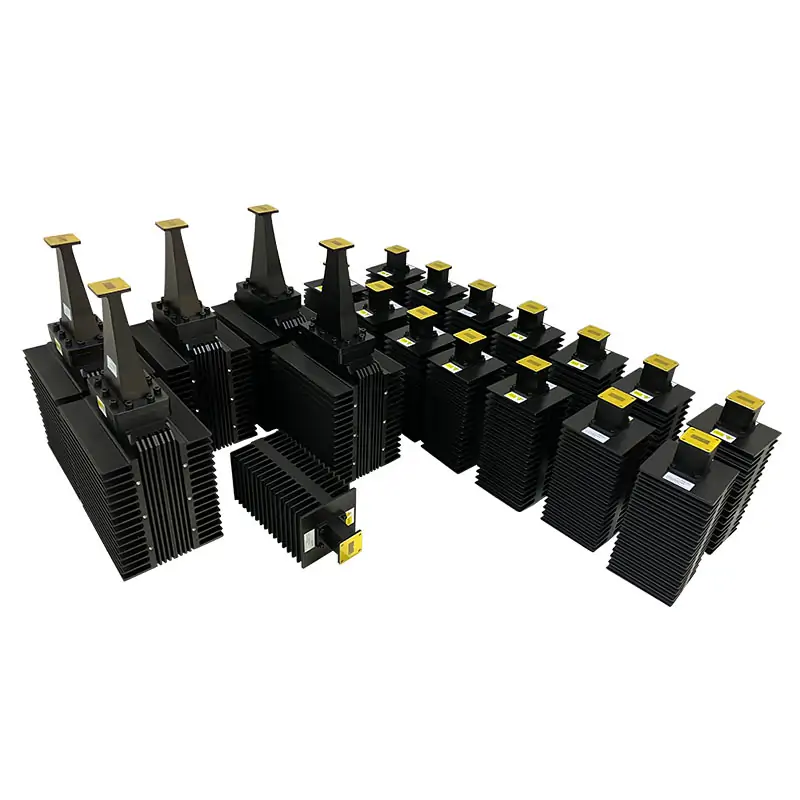
Dolph Microwave high power waveguide terminations absorb RF and microwave energy at the end of a rectangular waveguide path, helping reduce reflected power and protect transmitters, amplifiers, test equipment and other connected components. The published air-cooled range covers 1.13 to 112 GHz, WR650 to WR10, with model-dependent VSWR from 1.03:1 to 1.15:1 and continuous-wave ratings from 10 W to 4000 W. Aluminum or copper construction, cover or grooved flange configurations, IP65 protection, corrosion treatment and flat-black painted finishes are available according to model.
Reliable termination for high-power RF and microwave paths
The WHPL series is an air-cooled rectangular-waveguide load for safely absorbing incident RF and microwave power at the end of a waveguide line or on an unused output port.
The listed range covers WR650 to WR10, 1.13 to 112 GHz and 10 to 4000 W CW. A separate water-cooled product family is available for higher average-power requirements.
Product and flange reference files
Use the product PDF for the published range and the flange designation PDF to verify EIA/IEC mating interfaces.
Product range at a glance
Select from operating conditions, not WR size alone
Confirm the complete frequency band, flange interface, continuous and peak power, duty cycle, ambient temperature, available airflow and installation orientation before selecting the final model.
Frequency & WR Size
Match the complete operating band to the corresponding standard rectangular waveguide size.
Continuous Power
Provide continuous power, anticipated peak power and duty profile.
Cooling Conditions
Air-cooled models require sufficient ventilation and heat-release clearance.
Flange Interface
Confirm cover or grooved construction and the exact EIA/IEC designation.
Air-cooled model matrix
| Model | Freq. Range (GHz) | WG Size | VSWR | Avg. Power CW (W) | Cooling Method | Cover Flange | Grooved Flange | Ingress Protection | Material | Finish |
|---|---|---|---|---|---|---|---|---|---|---|
| DH-14WHPL… | 1.13–1.73 | WR650 | 1.03:1 | 1000–4000 | Air Cooled | UDR14 | PDR14 | IP65 | Al/Cu | Chromate/Painted |
| DH-18WHPL… | 1.45–2.2 | WR510 | 1.03:1 | 1000–3000 | Air Cooled | UDR18 | PDR18 | IP65 | Al/Cu | Chromate/Painted |
| DH-22WHPL… | 1.72–2.61 | WR430 | 1.03:1 | 100–3000 | Air Cooled | UDR22 | PDR22 | IP65 | Al/Cu | Chromate/Painted |
| DH-26WHPL… | 2.17–3.3 | WR340 | 1.03:1 | 100–3000 | Air Cooled | UDR26 | PDR26 | IP65 | Al/Cu | Chromate/Painted |
| DH-32WHPL… | 2.6–3.95 | WR284 | 1.03:1 | 100–3000 | Air Cooled | UDR32 | PDR32 | IP65 | Al/Cu | Chromate/Painted |
| DH-40WHPL… | 3.22–4.9 | WR229 | 1.03:1 | 100–3000 | Air Cooled | UDR40 | PDR40 | IP65 | Al/Cu | Chromate/Painted |
| DH-48WHPL… | 3.94–5.99 | WR187 | 1.03:1 | 100–3000 | Air Cooled | UDR48 | PDR348 | IP65 | Al/Cu | Chromate/Painted |
| DH-58WHPL… | 4.64–7.05 | WR159 | 1.03:1 | 100–3000 | Air Cooled | UDR58 | PDR58 | IP65 | Al/Cu | Chromate/Painted |
| DH-70WHPL… | 5.38–8.17 | WR137 | 1.03:1 | 100–3000 | Air Cooled | UDR70 | PDR70 | IP65 | Al/Cu | Chromate/Painted |
| DH-84WHPL… | 6.57–9.99 | WR112 | 1.03:1 | 100–3000 | Air Cooled | UDR84/UBR84 | PDR84/PBR84 | IP65 | Al/Cu | Chromate/Painted |
| DH-100WHPL… | 8.2–12.5 | WR90 | 1.03:1 | 100–3000 | Air Cooled | UDR100/UBR100 | PDR100/PBR100 | IP65 | Al/Cu | Chromate/Painted |
| DH-120WHPL… | 9.84–15 | WR75 | 1.03:1 | 100–3000 | Air Cooled | UBR120 | PBR120 | IP65 | Al/Cu | Chromate/Painted |
| DH-140WHPL… | 11.9–18 | WR62 | 1.03:1 | 100–3000 | Air Cooled | UBR140 | PBR140 | IP65 | Al/Cu | Chromate/Painted |
| DH-180WHPL… | 14.5–22 | WR51 | 1.03:1 | 100–2500 | Air Cooled | UBR180 | PBR180 | IP65 | Al/Cu | Chromate/Painted |
| DH-220WHPL… | 17.6–26.7 | WR42 | 1.03:1 | 100–2500 | Air Cooled | UBR220 | PBR220 | IP65 | Al/Cu | Chromate/Painted |
| DH-260WHPL… | 21.7–33 | WR34 | 1.03:1 | 100–2500 | Air Cooled | UBR260 | PBR260 | IP65 | Al/Cu | Chromate/Painted |
| DH-320WHPL… | 26.3–40 | WR28 | 1.03:1 | 100–2500 | Air Cooled | UBR320 | PBR320 | IP65 | Al/Cu | Chromate/Painted |
| DH-400WHPL… | 32.9–50.1 | WR22 | 1.15:1 | 100–1500 | Air Cooled | FUGP400 | UG-383U/M | IP65 | Al/Cu | Chromate/Painted |
| DH-500WHPL… | 39.2–59.6 | WR19 | 1.15:1 | 100–1500 | Air Cooled | FUGP500 | UG-383U/M | IP65 | Al/Cu | Chromate/Painted |
| DH-620WHPL… | 49.8–75.8 | WR15 | 1.15:1 | 100–1500 | Air Cooled | FUGP620 | UG-385U/M | IP65 | Al/Cu | Chromate/Painted |
| DH-740WHPL… | 60.5–91.9 | WR12 | 1.15:1 | 10–100 | Air Cooled | FUGP740 | UG-387U/M | IP65 | Al/Cu | Chromate/Painted |
| DH-900WHPL… | 73.8–112 | WR10 | 1.15:1 | 10–100 | Air Cooled | FUGP900 | UG-387U/M | IP65 | Al/Cu | Chromate/Painted |
Materials
Published material options are aluminum or copper, selected according to thermal, mass, conductivity and mechanical requirements.
Surface Protection
Published models include Surtec/corrosion protection treatment and flat-black paint. Flanges are unplated, polished and Surtec treated.
Flange Options
Cover and grooved flange designations are listed by model. Verify mating compatibility before ordering.
Capabilities available for component support
RF Measurement
Vector and scalar RF measurement capability up to 100 GHz, high-power transmitter resources and waveguide calibration service are listed on the company support page.
Environmental Testing
Published capabilities include temperature/altitude, salt fog/humidity, EMI and EMS testing.
Precision Manufacturing
Capabilities include CNC milling and turning, waveguide forming and bending, brazing, soldering, plating, passivation and assembly.
Technical reading for specification work
Waveguide Power Handling: CW, Peak Power, Breakdown and Cooling
Review practical power limits and thermal considerations.Waveguide Frequency Bands Chart: WR Sizes and Cutoff Frequency
Compare operating ranges before selecting the load size.Waveguide Flange Size Guide: EIA, IEC and Gasket Fit
Verify mating flange and gasket compatibility.Compatible products for the waveguide path
High Power Water-Cooled Loads
For substantially higher average-power dissipation.
Waveguide Termination
Review the broader termination product family.
High-Power Waveguide Coaxial Adapter
Transition between waveguide and coaxial interfaces.
Straight Waveguide Sections
Connect the load into a rigid transmission path.
Waveguide Flange Standard EIA & IEC
Check flange families and designation conventions.
Low Power Min (Short) Termination
A compact alternative for lower-power applications.
Provide the operating data required for model confirmation
Include frequency range, waveguide size, flange designation, continuous and peak power, duty cycle, installation orientation, ambient temperature, airflow conditions, material preference and any finish or dimensional constraints.
Contact Dolph Microwave