
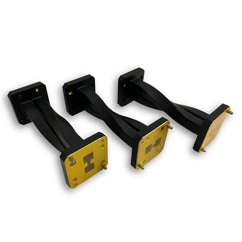
Waveguide Twists
Dolph Microwave double-ridged waveguide twists cover model-specific frequency bands from 0.84 GHz to 40.0 GHz across WRD840 to WRD180 waveguide sizes. Available configurations include 1.25:1 VSWR, model-dependent insertion loss, cover or grooved flanges, aluminum or copper construction, and right-handed or left-handed twist directions. The default twist angle is 90°, with other angles available on request.
Double-Ridged Waveguide Twist Specifications
Dolph Microwave waveguide twists are available for multiple double-ridged waveguide sizes and model-specific operating bands from 0.84 GHz to 40.0 GHz. Each listed model has a VSWR of 1.25:1, while insertion loss and minimum length vary according to the selected waveguide size.
Waveguide Twist Model Selection
Select the model by matching the complete operating frequency range, WRD waveguide size, flange designation, insertion-loss requirement and available installation length.
| Model | Frequency Range (GHz) | WG Size | VSWR | IL (dB) | Cover Flange | Grooved Flange | Minimum Length (mm) | Material | Finish | RoHS/REACH |
|---|---|---|---|---|---|---|---|---|---|---|
| DH-840DRWTA… | 0.84-2.0 | WRD840 | 1.25:1 | 0.2 | FPWRD840U24 | FMWRD840U24 | 500 | Al/Cu | Chromate/Painted | Comply |
| DH-150DRWTA… | 1.5-3.6 | WRD150 | 1.25:1 | 0.15 | FPWRD150D24 | FMWRD150D24 | 400 | Al/Cu | Chromate/Painted | Comply |
| DH-200DRWTA… | 2.0-4.8 | WRD200 | 1.25:1 | 0.15 | FPWRD200D24 | FMWRD200D24 | 400 | Al/Cu | Chromate/Painted | Comply |
| DH-250DRWTA… | 2.6-7.8 | WRD250 | 1.25:1 | 0.15 | FPWRD250D30 | FMWRD250D30 | 300 | Al/Cu | Chromate/Painted | Comply |
| DH-350DRWTA… | 3.5-8.2 | WRD350 | 1.25:1 | 0.25 | FPWRD350D24 | FMWRD350D24 | 300 | Al/Cu | Chromate/Painted | Comply |
| DH-475DRWTA… | 4.75-11.0 | WRD475 | 1.25:1 | 0.2 | FPWRD475D24 | FMWRD475D24 | 300 | Al/Cu | Chromate/Painted | Comply |
| DH-500DRWTA… | 5.0-18.0 | WRD500 | 1.25:1 | 0.5 | FPWRD500D36 | FMWRD500D36 | 200 | Al/Cu | Chromate/Painted | Comply |
| DH-580DRWTA… | 5.8-16.0 | WRD580 | 1.25:1 | 0.35 | FPWRD580D28 | FMWRD580D28 | 200 | Al/Cu | Chromate/Painted | Comply |
| DH-650DRWTA… | 6.5-18.0 | WRD650 | 1.25:1 | 0.35 | FPWRD650D28 | FMWRD650D28 | 200 | Al/Cu | Chromate/Painted | Comply |
| DH-700DRWTA… | 7.0-18.5 | WRD700 | 1.25:1 | 0.4 | FPWRD700D26 | FMWRD700D26 | 200 | Al/Cu | Chromate/Painted | Comply |
| DH-750DRWTA… | 7.5-18.0 | WRD750 | 1.25:1 | 0.6 | FPWRD750D24 | FMWRD750D24 | 200 | Al/Cu | Chromate/Painted | Comply |
| DH-110DRWTA… | 11.0-26.5 | WRD110 | 1.25:1 | 0.75 | FPWRD110C24 | FMWRD110C24 | 150 | Al/Cu | Chromate/Painted | Comply |
| DH-180DRWTA… | 18.0-40.0 | WRD180 | 1.25:1 | 1.5 | FPWRD180C24 | FMWRD180C24 | 80 | Al/Cu | Chromate/Painted | Comply |
How to Select a Waveguide Twist
Match the Operating Band
Select a model whose listed frequency range covers the complete required operating band. Where multiple models overlap in frequency, confirm the WRD waveguide size before selecting a model.
Confirm the Waveguide Size
The waveguide size must match the adjoining components. Available sizes include WRD840, WRD150, WRD200, WRD250, WRD350, WRD475, WRD500, WRD580, WRD650, WRD700, WRD750, WRD110 and WRD180.
Review Insertion Loss
Insertion loss varies from 0.15 dB to 1.5 dB across the listed models. Use the value shown in the corresponding model row.
Check Minimum Length
The listed minimum lengths range from 80 mm to 500 mm. Confirm the available installation space before finalizing the configuration.
Select the Flanges
Each model includes separate cover-flange and grooved-flange designations. Confirm the required interfaces at both ends of the waveguide twist.
Specify Angle and Direction
The default twisting angle is 90°. Other angles are available on request. Specify whether a right-handed or left-handed twist is required.
Waveguide Twist Configuration
Twist Angle and Direction
The default twist angle is 90°. Twist angles other than 90° are available on request.
- WTA: Rectangular right-handed twisted waveguide
- WLTA: Rectangular left-handed twisted waveguide
The twist direction is selected by Dolph Microwave unless otherwise specified. Include the required direction in the RFQ when a specific configuration is needed.
Materials and Surface Finish
The listed waveguide twists are available in aluminum or copper. All models include Surtec/corrosion-protection treatment and are painted flat black.
The flanges are unplated, polished and Surtec-treated. Other finishes and paint colors are available on request.
Part Number Guide
- 840DR — Waveguide size: WRD840
- WTA — Rectangular right-handed twisted waveguide
- WLTA — Rectangular left-handed twisted waveguide
- 500 — Length: 500 mm
- P — Rectangular flat flange
- M — Rectangular grooved flange
- A/C — Aluminum or copper
- 45 — 45° twisting angle
Waveguide Twist Downloads
Use the following documents to review the available waveguide twist configurations and double-ridged flange designations.
Waveguide Twists
Review the model ranges, waveguide sizes, flange options, minimum lengths, materials and part-number information.
Download Waveguide Twists PDFDouble-Ridged Flange Type Designations
Review the applicable double-ridged waveguide flange designations when confirming the required interface.
Download Flange Designations PDFWaveguide Twist FAQs
What frequency ranges are available?
The listed models cover individual operating ranges from 0.84-2.0 GHz through 18.0-40.0 GHz. Select a model according to both the frequency range and the required WRD waveguide size.
What is the VSWR of the listed models?
The supplied product table lists a VSWR of 1.25:1 for every model.
What is the standard twist angle?
The default twisting angle is 90°. Other twist angles are available on request.
Are right-handed and left-handed waveguide twists available?
Yes. WTA identifies a rectangular right-handed twisted waveguide, while WLTA identifies a rectangular left-handed twisted waveguide.
What flange types are available?
The listed models support cover and grooved flange configurations. The exact flange designation varies according to the selected waveguide size.
What materials and finishes are available?
The listed material options are aluminum and copper. Standard information includes Surtec/corrosion-protection treatment and flat-black paint. Other finishes and paint colors are available on request.
Request a Waveguide Twist Quote
Include the following information in your RFQ so the required waveguide twist configuration can be identified accurately:
- Operating frequency range
- WRD waveguide size
- Required twist angle
- Right-handed or left-handed direction
- Input and output flange designations
- Required length
- Aluminum or copper material
- Required finish or paint color
- Required quantity
- PDF drawing, STEP model and RoHS/REACH documentation requirements
Send these specifications through the existing quotation or contact form on the product page.







