
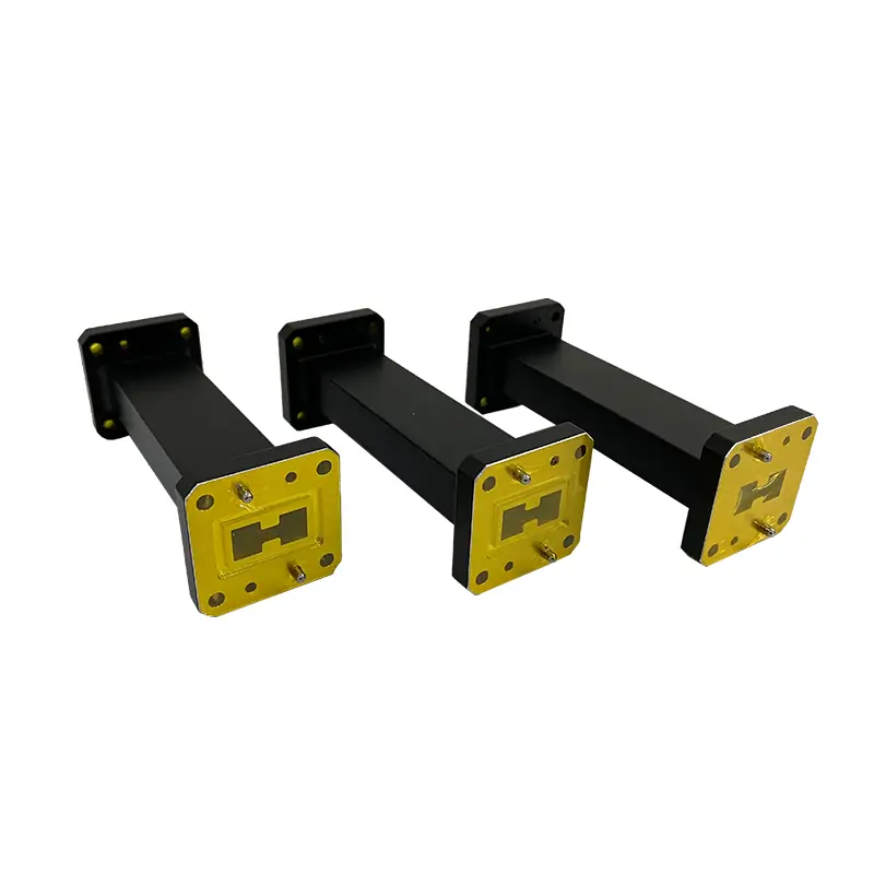
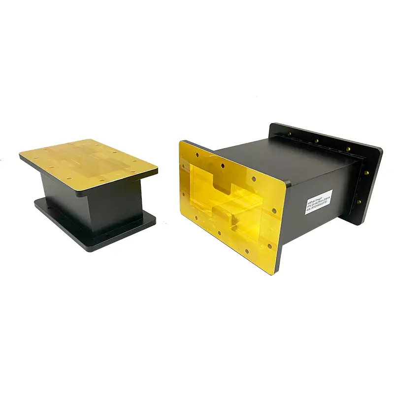
Double Ridge Waveguide-Transition
Dolph Microwave’s precision-engineered waveguide transitions enable seamless connectivity between double-ridge waveguides from 3.5 GHz to 18 GHz, delivering industry-leading performance with VSWR as low as 1.08:1 and minimal insertion loss. Designed for high-power applications like radar, SATCOM, and aerospace systems, these rugged adapters (WRD-350 to WRD750) feature gold-plated brass or corrosion-resistant aluminum construction, ensuring reliable signal integrity in harsh environments. Trust Dolph Microwave for mission-critical solutions where precision, low reflection, and broad frequency coverage are paramount.
Double-Ridge Waveguide Transitions for Low-Loss System Integration
Dolph Microwave’s Double-Ridge Waveguide Transitions provide high-performance interconnects for seamless signal transmission between double-ridge waveguide systems operating across 3.5 GHz to 18 GHz. Engineered for precision, these adapters minimize insertion loss (typical VSWR ≤1.15:1) while ensuring optimal impedance matching across overlapping and multi-band frequency ranges. Constructed from robust gold-plated or corrosion-resistant painted brass, they are ideal for high-power applications requiring reliability in harsh environments, such as radar, SATCOM, and MILCOM systems. With waveguide sizes spanning WRD-350 to WRD750, these transitions support flexible system integration while maintaining signal integrity up to 18 GHz.
Controlled Transition Between Double-Ridge Waveguide Interfaces
The waveguide transitions feature a tapered design for smooth modal conversion, reducing reflections and achieving a voltage standing wave ratio (VSWR) as low as 1.08:1 across specified bands. Rugged aluminum or brass construction, combined with Surtec corrosion-resistant treatment and flat-black paint, ensures durability in outdoor or high-humidity deployments. Flange configurations include flat (FPWRD) and grooved types, compliant with MIL-STD standards for secure mating. Customizable finishes and materials are available to meet specific environmental or electrical requirements.
Tapered RF Transition
A controlled taper supports smooth modal conversion between different double-ridge waveguide sizes while reducing discontinuity-related reflections.
Low-Reflection Performance
The listed standard models specify VSWR up to 1.15, while selected designs may achieve lower values across their specified operating bands.
Multiple Flange Options
Flat and grooved flange arrangements support secure mating with compatible double-ridge waveguide components.
Corrosion Protection
Surtec treatment and flat-black paint are used on listed configurations, with other finishes and paint colors available upon request.
Custom Mechanical Length
Transition length can be reviewed against waveguide sizes, required electrical performance and the available installation envelope.
Material Flexibility
Listed models use aluminum, while aluminum, copper and other requested material or finish combinations can be reviewed for custom applications.
Low-Loss Connections for Multi-Band RF Systems
These adapters are critical in aerospace telemetry, scientific research instrumentation, and telecom infrastructure where multi-band waveguide systems demand low-loss transitions. Their ability to handle high power densities (up to 1 kW average) makes them suitable for radar pulse transmission, satellite ground stations, and RF testing environments requiring repeatable performance.
Radar Systems
Connects different double-ridge waveguide sections in broadband radar transmit and receive chains.
SATCOM and Ground Stations
Supports integration of broadband waveguide subsystems in satellite communication and ground-terminal equipment.
MILCOM Systems
Provides mechanical and electrical compatibility between selected double-ridge waveguide sizes in communication assemblies.
RF Test Systems
Enables repeatable interconnection of broadband waveguide components in laboratory and production-test setups.
Scientific Instrumentation
Supports broadband measurement systems that require controlled transitions between different double-ridge interfaces.
Aerospace Telemetry
Integrates broadband RF paths where size, interface compatibility and repeatable electrical performance are important.
Match Both Waveguide Ports and the Shared Operating Band
A double-ridge transition must be selected around the common usable frequency range of both connected waveguide systems. The waveguide designation alone is not enough; flange geometry, transition length, VSWR target, material and finish must also be confirmed.
Confirm Port 1
Specify the first waveguide family and its exact flange designation.
Confirm Port 2
Specify the second waveguide family, flange and mating arrangement.
Define the Band
Provide the actual minimum and maximum operating frequencies.
Review Length
Check the available envelope and required transition length.
Set Requirements
State VSWR, power, material, finish and documentation needs.
Do Not Select by WRD Size Alone
- Port 1 waveguide and flange
- Port 2 waveguide and flange
- Shared usable frequency range
- Maximum allowable VSWR
- Average and peak power
- Mechanical length and mounting
- Material, finish and environment
Material, Finish and Interface Options
All transitions comply with RoHS and REACH regulations. Optional finishes, including MIL-SPEC gold plating or custom paint colors, are available upon request. For detailed mechanical drawings and electrical performance data, refer to the product datasheets or contact Dolph Microwave’s engineering team for application-specific solutions.
Information to Provide
- Port 1 and Port 2 WRD sizes
- Flange designations
- Operating frequency range
- VSWR and power requirements
- Required length or envelope
- Material and finish
- Quantity and delivery schedule
- Drawing or STEP-file requirements
Double-Ridge Waveguide Transition Specifications
Scroll horizontally on smaller screens to view every specification column. Final model designation, mechanical drawing and STEP file should be confirmed before ordering.
| MODEL | FREQ. RANGE (GHz) |
VSWR | LENGTH (mm) |
PORT 1 WAVEGUIDE / FLANGE TYPE |
PORT 2 WAVEGUIDE / FLANGE TYPE |
MATERIAL | FINISH | ROHS & REACH | DATASHEET | |||
|---|---|---|---|---|---|---|---|---|---|---|---|---|
| DH-250DRT350WA… | 3.50-5.80 | 1.15 | 200 | WRD250 | FPWRD250D30 | WRD350 | FPWRD350D24 | Al | Chromate/Painted | Comply | DWG | STEP |
| DH-475DRT500WA… | 5.0-11.0 | 1.15 | 130 | WRD475 | FPWRD475D24 | WRD500 | FPWRD500D36 | Al | Chromate/Painted | Comply | DWG | STEP |
| DH-475DRT580WA… | 5.8-11.0 | 1.15 | 130 | WRD475 | FPWRD475D24 | WRD580 | FPWRD580D28 | Al | Chromate/Painted | Comply | DWG | STEP |
| DH-475DRT650WA… | 6.5-11.0 | 1.15 | 135 | WRD475 | FPWRD475D24 | WRD650 | FPWRD650D28 | Al | Chromate/Painted | Comply | DWG | STEP |
| DH-475DRT750WA… | 7.50-11.0 | 1.15 | 135 | WRD475 | FPWRD475D24 | WRD750 | FPWRD750D24 | Al | Chromate/Painted | Comply | DWG | STEP |
| DH-500DRT580WA… | 5.8-16.0 | 1.15 | 135 | WRD500 | FPWRD500D36 | WRD580 | FPWRD580D28 | Al | Chromate/Painted | Comply | DWG | STEP |
| DH-500DRT650WA… | 6.5-18.0 | 1.15 | 130 | WRD500 | FPWRD500D36 | WRD650 | FPWRD650D28 | Al | Chromate/Painted | Comply | DWG | STEP |
| DH-500DRT750WA… | 7.5-18.0 | 1.15 | 180 | WRD500 | FPWRD500D36 | WRD750 | FPWRD750D24 | Al | Chromate/Painted | Comply | DWG | STEP |
| DH-580DRT650WA… | 6.5-16.0 | 1.15 | 150 | WRD580 | FPWRD580D28 | WRD650 | FPWRD650D28 | Al | Chromate/Painted | Comply | DWG | STEP |
| DH-580DRT750WA… | 7.5-16.0 | 1.15 | 130 | WRD580 | FPWRD580D28 | WRD750 | FPWRD750D24 | Al | Chromate/Painted | Comply | DWG | STEP |
| DH-650DRT750WA… | 7.5-18.0 | 1.15 | 125 | WRD650 | FPWRD650D28 | WRD750 | FPWRD750D24 | Al | Chromate/Painted | Comply | DWG | STEP |
Example: DH-500DRT650WA130PPA
All Dolph-MW models include a Surtec/corrosion protection treatment and are painted flat black. Flanges are unplated, polished and Surtec treated. Other finishes and paint colors are available upon request.
Reference Documents
Use the available PDF documents together with the approved model drawing and flange designation when confirming the required configuration.







