
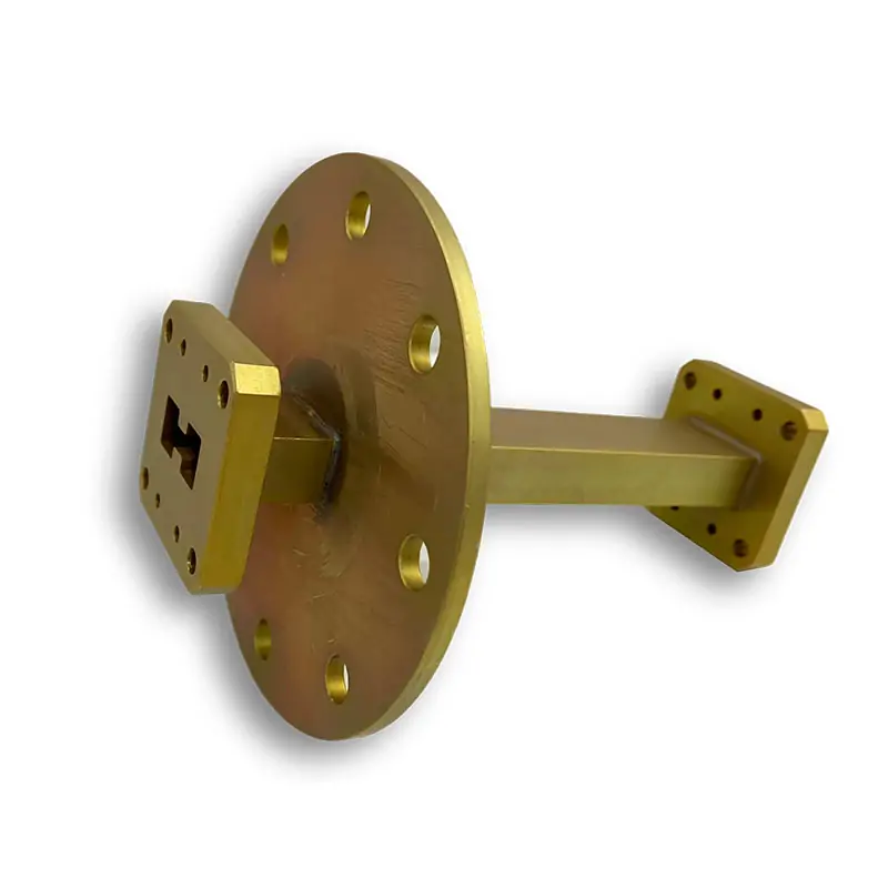
Waveguide Bulkhead Feedthrus
Double-ridged waveguide bulkhead feedthroughs provide a waveguide path through equipment walls and mounting panels. Select one of 13 model ranges, then confirm the flange drawing, installation dimensions and configuration-specific RF limits.
Double-Ridged Waveguide Bulkhead Feedthroughs
Dolph Microwave waveguide bulkhead feedthroughs route a double-ridged waveguide connection through an equipment wall, mounting panel, or enclosure partition.
The product brochure lists 13 double-ridged models with combined coverage from 0.84 to 40.0 GHz. Each row below gives its own frequency range, maximum VSWR, maximum insertion loss and catalogue length. Cover and grooved flange configurations are available.
Select the complete operating band, WRD size, flange pair and panel dimensions. A mechanical feedthrough does not by itself specify a gas-tight or waterproof barrier; define any pressure differential, leak-rate limit and sealing arrangement separately.
Waveguide Bulkhead Feedthrough Specifications
The following values are transcribed from the Dolph product brochure, printed pages 023–024. Maximum VSWR is 1.05:1 and maximum insertion loss is 0.1 dB for each listed model. Catalogue lengths are reproduced in millimetres; use the order drawing for mounting details and tolerances.
| Model | WR Type | Frequency (GHz) | VSWR Max. | IL Max. (dB) | Length (mm) | Assemblies |
|---|---|---|---|---|---|---|
| DH-84DRBFU… | WRD84 | 0.84–2.0 | 1.05 | 0.1 | 250 | Hardware/Gasket |
| DH-150DRBFU… | WRD150 | 1.5–3.6 | 1.05 | 0.1 | 250 | Hardware/Gasket |
| DH-200DRBFU… | WRD200 | 2.0–4.8 | 1.05 | 0.1 | 250 | Hardware/Gasket |
| DH-250DRBFU… | WRD250 | 2.6–7.8 | 1.05 | 0.1 | 250 | Hardware/Gasket |
| DH-350DRBFU… | WRD350 | 3.5–8.2 | 1.05 | 0.1 | 250 | Hardware/Gasket |
| DH-475DRBFU… | WRD475 | 4.75–11.0 | 1.05 | 0.1 | 108 | Hardware/Gasket |
| DH-500DRBFU… | WRD500 | 5.0–18.0 | 1.05 | 0.1 | 95 | Hardware/Gasket |
| DH-580DRBFU… | WRD580 | 5.8–16.0 | 1.05 | 0.1 | 95 | Hardware/Gasket |
| DH-650DRBFU… | WRD650 | 6.5–18.0 | 1.05 | 0.1 | 95 | Hardware/Gasket |
| DH-750DRBFU… | WRD750 | 7.5–18.0 | 1.05 | 0.1 | 95 | Hardware/Gasket |
| DH-700DRBFU… | WRD700 | 7.0–18.0 | 1.05 | 0.1 | 95 | Hardware/Gasket |
| DH-110DRBFU… | WRD110 | 11.0–26.5 | 1.05 | 0.1 | 76 | Hardware/Gasket |
| DH-180DRBFU… | WRD180 | 18.0–40.0 | 1.05 | 0.1 | 76 | Hardware/Gasket |
How to Select a Waveguide Bulkhead Feedthrough
Match the Complete Frequency Range
Select a model whose listed frequency range covers the complete operating band. Do not select a model only according to the nominal or center frequency.
Confirm the Waveguide Size
The feedthrough WRD size should match the adjoining double-ridged waveguide components. Overlapping frequency ranges do not make different waveguide sizes mechanically interchangeable.
Verify Both Flange Interfaces
Check aperture, ridge gap, bolt pattern, locating pins and sealing faces on both mating drawings. In the flange PDF, the WRD110 and WRD180 headings use D24 while the drawing labels use C24; the WRD700 heading also gives an inconsistent mating code. Confirm those specific interfaces on the order drawing.
Check the Installation Dimensions
The brochure lists lengths of 250, 108, 95 or 76 mm, depending on the model. Check panel thickness, fastener access, mounting-hole positions and clearances on the dimensioned order drawing; the brochure does not supply machining tolerances.
Materials, Flanges and Surface Finish
Material Selection
The brochure’s features and description list aluminum and copper, while its finish table lists Al/Brass. Its ordering example explicitly identifies A as aluminum. Specify the required alloy on the order; the PDF does not resolve the copper-versus-brass entry.
Cover and Grooved Flanges
The product brochure offers cover and grooved flanges. Select both interfaces from the mating drawings, including the sealing arrangement and ridge geometry.
Standard Body Treatment
Corrosion protection and flat-black body paint are catalog finish options. Specify the coating or plating process, base alloy and masked contact surfaces. MIL-DTL-5541 covers conversion coatings on aluminum and aluminum alloys; it is not a copper or brass material specification.[1]
Flange and Finish Options
Define the finish of the flange contact faces separately from the body paint. Confirm whether those faces are polished, conversion-coated or plated for the selected alloy; specify other finishes and paint colors in the request.
Waveguide Bulkhead Feedthru Part Number Guide
- DH — Dolph Microwave
- 650DR — WRD650 waveguide size
- BFU — Waveguide bulkhead feedthrough
- 100 — Example length: 100 mm
- P — Cover flange
- M — Grooved flange
- A — Aluminum
Provide the required frequency range, WRD waveguide size, flange arrangement, material, and installation dimensions when requesting the final orderable part number.
Quality Documentation for the Selected Part
For supplier qualification, request the current quality-system certificate, its validity and its covered activities. ISO 9001 addresses a quality management system; it does not establish this part’s VSWR, pressure rating or RF power limit.[2]
For product acceptance, specify the required material record, dimensional inspection and RF test report in the purchase requirements.
Technical Downloads
Waveguide Bulkhead Feedthrus
This brochure is the source for the model table above, including frequency, maximum VSWR, maximum insertion loss and catalogue length. The material discrepancy within the PDF is identified in the material section.
Download Product DatasheetDouble-Ridged Flange Type Designations
Check flange geometry in the drawings. Resolve the WRD110/WRD180 heading discrepancies and the WRD700 mating-flange heading against the approved interface drawing.
Download Flange DesignationsFrequently Asked Questions
Can one feedthrough cover the full 0.84–40 GHz range?
No. That is the combined coverage of 13 catalog models. Select a row covering both band edges and confirm performance at those endpoints.
Does the feedthrough isolate pressure on opposite sides of a wall?
An open waveguide passage does not isolate gas pressure. If separate pressure zones are required, specify a compatible pressure window plus the flange and panel seals, differential pressure and leak test.
Which VSWR limit should an acceptance test use?
The product brochure specifies a maximum VSWR of 1.05:1 for all 13 listed models. Include that limit and the model’s full frequency band in the purchase requirements, together with the calibrated reference planes and required RF test record.
What RF power can this part handle?
No configuration-specific power rating is established by this table. State CW average power, pulse peak power, pulse width, duty cycle, gas pressure and temperature; request a rating for those conditions.
Will overlapping frequency ranges make two WRD sizes compatible?
No. Match the aperture and ridge geometry as well as the flange. If adjoining sizes differ, specify an RF transition with the required band and verified end interfaces.
What should be checked after panel mounting?
Check alignment and support before tightening the mating assembly. Use the approved fastener procedure, then check assembled RF performance and any specified leak test; do not pull misaligned components together with flange bolts.
Continue the Waveguide System Design
Request a Waveguide Bulkhead Feedthrough Quote
Provide the main electrical and mechanical requirements so the applicable catalog model and configuration can be reviewed.
- Operating frequency range
- Required WRD waveguide size
- Flange configuration on each side
- Required base alloy
- Available installation dimensions
- Required finish or paint color
- Prototype or production quantity
- Required delivery date







