
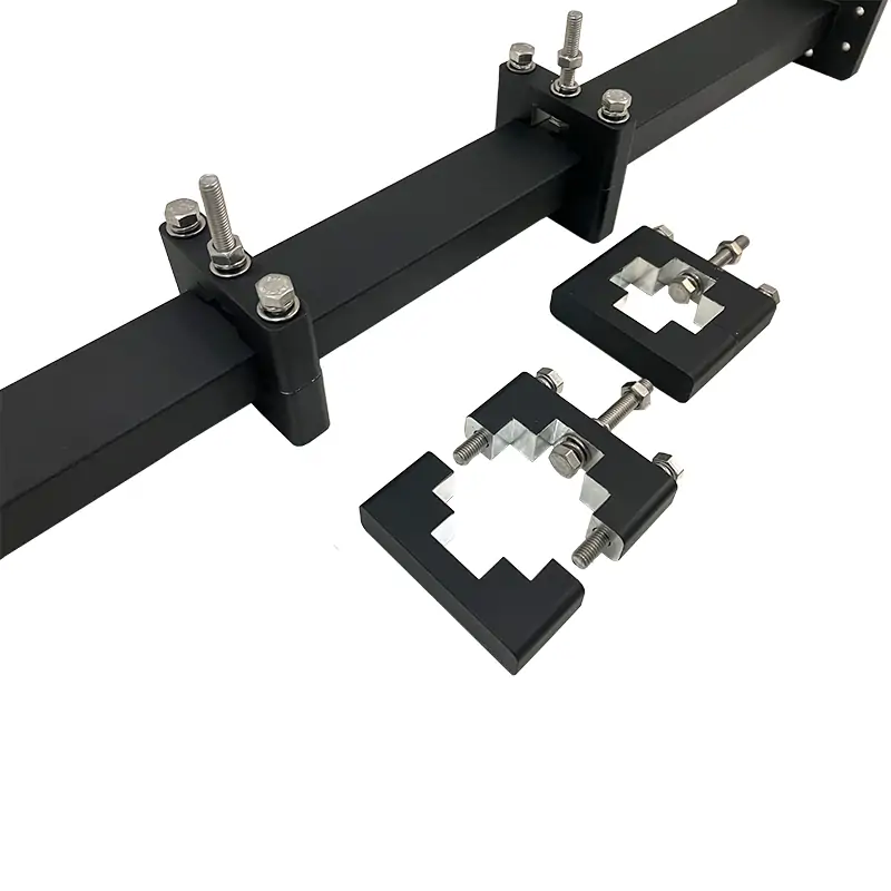
WG Standoff and Hangers
Dolph Microwave’s Double-Ridge Waveguide Standoffs and Hangers provide robust mechanical support for E/H-plane waveguide alignment across 0.84–40 GHz (e.g., WRD840 to WRD180 models). Constructed with lightweight aluminum and corrosion-resistant stainless steel hardware, these clamps feature Surtec chromate coating and RoHS/REACH compliance for harsh environments. Ideal for radar, satellite communications, and aerospace applications, they ensure minimal signal loss and include pre-assembled kits for rapid deployment. Custom waveguide sizes and finishes are available to meet specialized project requirements.
Double-Ridge Waveguide Standoffs and Hangers
Dolph Microwave’s Double-Ridge Waveguide Standoffs and Hangers are precision-engineered aluminum clamps designed to secure waveguides in E-plane or H-plane configurations across critical RF and microwave systems.
Compatible with standard WRD waveguide sizes, including models from WRD840 to WRD180, these components cover waveguide systems operating from 0.84 GHz to 40 GHz. Each unit includes corrosion-resistant stainless steel hardware and receives a Surtec chromate conversion treatment with flat-black paint for durability in demanding installation environments.
Stable Mechanical Support for Waveguide Systems
Engineered for versatility, these standoffs and hangers integrate with rectangular and double-ridge waveguides while providing secure mechanical positioning in indoor and outdoor installations.
E-Plane or H-Plane Mounting
The clamp geometry supports waveguide positioning in E-plane or H-plane orientations, depending on system layout and installation requirements.
Lightweight Aluminum Body
Aluminum construction reduces installed weight while maintaining the mechanical strength required to support waveguide routing and alignment.
Stainless Steel Hardware
Corrosion-resistant stainless steel mounting kits support long-term installation reliability in laboratory, telecom, radar and aerospace systems.
Pre-Assembled Mounting Hardware
Pre-assembled hardware reduces installation steps and supports faster deployment during waveguide assembly and system integration.
Corrosion-Resistant Finish
Surtec chromate conversion treatment and flat-black paint provide surface protection for demanding indoor and outdoor environments.
Custom Configuration Support
Alternative finishes, paint colors, materials and non-standard waveguide dimensions can be reviewed for project-specific requirements.
Waveguide Alignment and Installation Planning
Standoff and hanger selection should be based on waveguide size, support spacing, mounting orientation, available installation space and the operating environment.
Waveguide Size Matching
Each model is dimensioned for a corresponding WRD waveguide size. Confirm the actual waveguide body dimensions rather than selecting only by operating frequency.
Support Spacing
Required hanger spacing depends on waveguide length, routing direction, system vibration, mounting surface and the weight of connected components.
Indoor and Outdoor Installation
The aluminum body, chromate treatment, painted surface and stainless steel hardware support installations that may be exposed to humidity, temperature changes and outdoor conditions.
Custom Installation Geometry
Provide the waveguide outline, mounting-hole arrangement, support surface and available clearance when a standard standoff or hanger cannot be used.
Typical RF and Microwave System Uses
These components are used wherever waveguide positioning and mechanical alignment must be maintained throughout installation and operation.
Application
Deployed in high-performance systems, these components are critical for maintaining waveguide alignment in radar arrays, satellite communication ground stations, and aerospace telemetry. They are equally suited for scientific research applications, such as particle accelerator RF systems, where precise waveguide positioning is essential.
Radar Arrays
Mechanical support for waveguide routing between radar antennas, transmitters, receivers and distribution assemblies.
Satellite Ground Stations
Waveguide support in antenna-feed networks, ground-terminal equipment and high-frequency communication infrastructure.
Aerospace Telemetry
Lightweight mechanical support for waveguide installations in aerospace communication and telemetry systems.
Scientific RF Systems
Precise waveguide positioning for particle accelerators, research laboratories and other scientific microwave systems.
Standard Double-Ridge Waveguide Standoff and Hanger Models
The supplied product range contains 13 standard models covering frequencies from 0.84 GHz with the DH-840DRWSH to 40 GHz with the DH-180DRWSH.
For example, the DH-250DRWSH operates at 2.6–7.8 GHz with a WRD250 waveguide and has published dimensions of 22.42 mm for A, 46.35 mm for B, and 127 mm for C and D. All listed models use a 12.7 mm E dimension and are supplied with corrosion-resistant chromate and painted finishes. CAD model formats include DWG and STEP.
| MODEL |
FREQ. RANGE (GHz) |
WG SIZE | DIMENSIONS (mm) | MATERIAL | FINISH |
ROHS & REACH |
DATASHEET | |||||
|---|---|---|---|---|---|---|---|---|---|---|---|---|
| A | B | C | D | E | ||||||||
| DH-840DRWSH… | 0.84-2.0 | WRD840 | 79.4 | 163.5 | 241.9 | 241.9 | 12.7 | Al | Chromate/Painted | Comply | DWG | STEP |
| DH-150DRWSH… | 1.5-3.6 | WRD150 | 45.1 | 92.05 | 171.45 | 171.45 | 12.7 | Al | Chromate/Painted | Comply | DWG | STEP |
| DH-200DRWSH… | 2.0-4.8 | WRD200 | 34.87 | 70.05 | 139.7 | 139.7 | 12.7 | Al | Chromate/Painted | Comply | DWG | STEP |
| DH-250DRWSH… | 2.6-7.8 | WRD250 | 22.42 | 46.35 | 127 | 127 | 12.7 | Al | Chromate/Painted | Comply | DWG | STEP |
| DH-350DRWSH… | 3.5-8.2 | WRD350 | 20.93 | 40.05 | 114.3 | 114.3 | 12.7 | Al | Chromate/Painted | Comply | DWG | STEP |
| DH-475DRWSH… | 4.75-11.0 | WRD475 | 15.59 | 30.43 | 101.6 | 101.6 | 12.7 | Al | Chromate/Painted | Comply | DWG | STEP |
| DH-500DRWSH… | 5.0-18.0 | WRD500 | 10.94 | 21.84 | 31.88 | 31.88 | 12.7 | Al | Chromate/Painted | Comply | DWG | STEP |
| DH-580DRWSH… | 5.8-16.0 | WRD580 | 12.05 | 22.55 | 63.6 | 63.5 | 12.7 | Al | Chromate/Painted | Comply | DWG | STEP |
| DH-650DRWSH… | 6.5-18.0 | WRD650 | 10.89 | 21.05 | 63.6 | 63.5 | 12.7 | Al | Chromate/Painted | Comply | DWG | STEP |
| DH-700DRWSH… | 7.0-18.5 | WRD700 | 10.89 | 20.2 | 50.8 | 50.8 | 12.7 | Al | Chromate/Painted | Comply | DWG | STEP |
| DH-750DRWSH… | 7.5-18.0 | WRD750 | 10.61 | 20.3 | 50.8 | 50.8 | 12.7 | Al | Chromate/Painted | Comply | DWG | STEP |
| DH-110DRWSH… | 11.0-26.5 | WRD110 | 7.79 | 14.2 | 50.8 | 50.8 | 12.7 | Al | Chromate/Painted | Comply | DWG | STEP |
| DH-180DRWSH… | 18.0-40.0 | WRD180 | 5.64 | 9.55 | 50.8 | 50.8 | 12.7 | Al | Chromate/Painted | Comply | DWG | STEP |
Part Number Guide
WRD840
Standoff and Hangers
Aluminum
Durable Plastic
Materials, Finishes and Project Options
Every unit undergoes Surtec 650/651 chromate conversion coating for enhanced corrosion resistance, with flanges polished to minimize RF leakage. Standard models are painted flat black, but alternative colors or finishes, including powder coating, can be specified. Dolph Microwave’s engineering team supports custom designs for unique waveguide geometries or environmental requirements.
All Dolph Microwave models include a Surtec corrosion-protection treatment and are painted flat black. Flanges are unplated, polished and Surtec treated. Other finishes and paint colors are available upon request.
Information to Confirm Before Ordering
Include the following information with your inquiry so the mounting configuration can be reviewed against the waveguide system and installation environment.
Provide the WRD designation and actual outside dimensions.
Confirm whether E-plane or H-plane support is required.
Provide the support-frame, wall, rack or platform arrangement.
State whether the installation is indoor, outdoor or exposed to vibration.
Specify paint color, coating or corrosion-protection requirements.
Provide the required quantity and whether DWG or STEP files are needed.
Supporting Waveguide Documents
Access the existing technical files retained from the original product-page content.
Request a Waveguide Support Configuration
Provide the waveguide size, mounting orientation, support spacing, installation environment and required quantity. Dolph Microwave can review standard standoff and hanger models or develop custom configurations for specialized waveguide geometries and environmental requirements.







