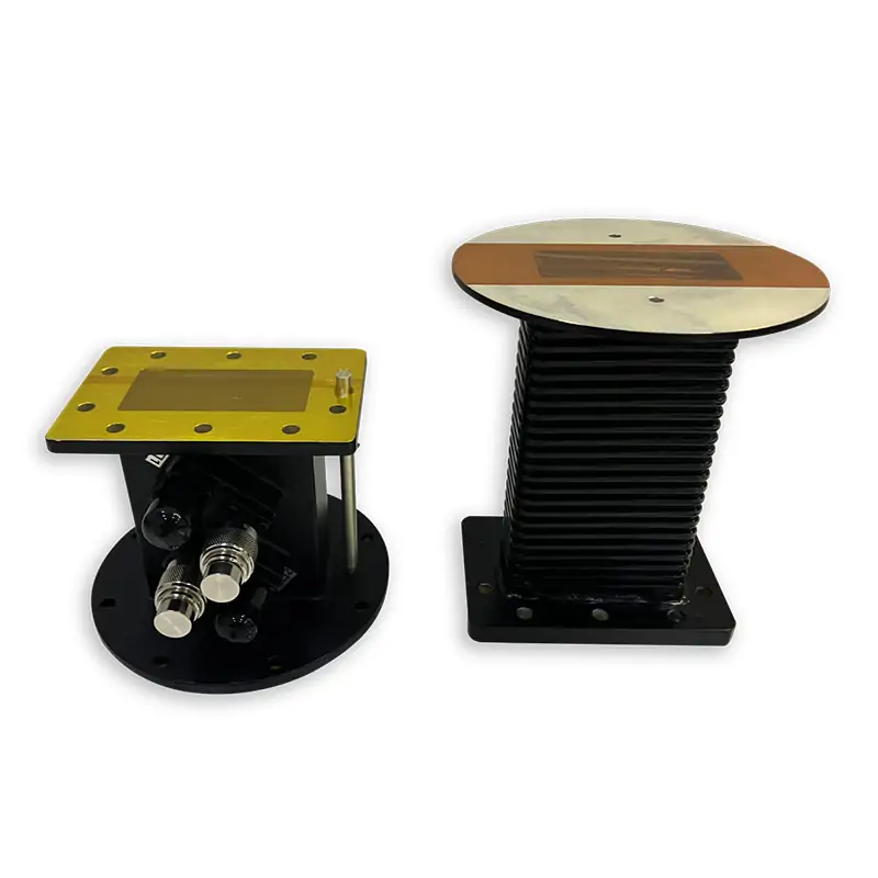
915 & 2450 MHz Microwave Coupler
Take a small sample of the power in your microwave line. Choose the coupling level, connector and waveguide size to suit your meter or monitoring system.
What do you need to measure?
Start with the signal you want to see at the measurement port. Then match the coupler to the power in the main line and the input limits of your instrument.
Start with the operating limits
| Specification | Details |
|---|---|
| Frequency Range | 915 MHz and 2450 MHz |
| Handling Power | 6 KW, 10 KW, up to 20 KW cw |
| Bandwidth | 20% |
| Coupling Degree | 30-70 dB |
| Directivity | 20-25 dB |
| Structure | Compact |
These are the published feature specifications. Check the detailed model data below for the configuration you need.
Measuring a mismatch and adjusting it are different jobs
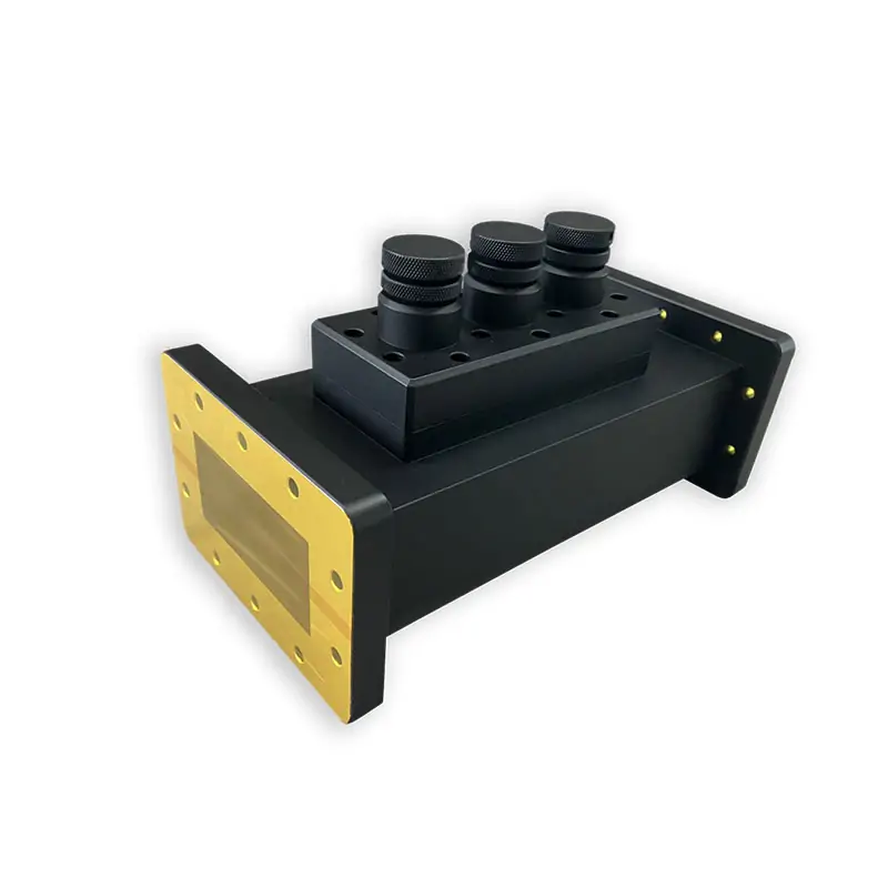
A coupler gives you a sample for measurement. A tuner adjusts the load match. If you need both functions, check the measurement connection as well as the space needed to reach the tuner adjustments.
See the microwave tuners for load matching.
If reflected power also needs to be managed, compare the microwave isolator. For different waveguide sizes at the mating ends, review the waveguide transition options.
Check the fit before placing the order
Electrical ratings are not enough if the flanges, connectors or mounting points do not fit. A marked-up drawing is the clearest way to show the space you have.
Replacing a coupler
Send the old part number, a clear connector photo and the dimensions between mating flanges. A similar-looking housing does not establish the same coupling or interface.
Building a new line
Send the operating frequency, continuous power and measurement task. Add the available space and cable connection you plan to use.
Use the flange designation guide when naming the mating connection. Include a photo if the flange code is not known.
Agree on the build and the checks
Dolph’s manufacturing work includes CNC machining, turning, waveguide forming, brazing, plating and assembly. For a custom part, send the drawing requirements and the checks your team needs before ordering.
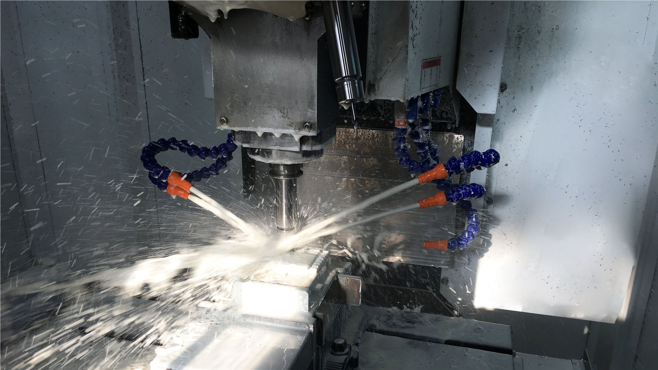

If you need dimensional results, RF measurements or specific inspection records, list them with your enquiry. Confirm the scope with the selected configuration. See Dolph’s manufacturing capabilities.
Full model and construction details
Compare the frequency, waveguide, connection and material before choosing a model. Send the catalogue reference if an entry matches your requirement.
Waveguide and coupling models
| Model | WR Type | Frequency (MHZ) | VSWR Max. | Coupling (dB) |
|---|---|---|---|---|
| DH-9WHC | WR975 | 915±50 | 1.1 | 30-70 |
| DH-22WHC… | WR430 | 2450±50 | 1.1 | 30-70 |
| DH-26WHC… | WR340 | 2450±50 | 1.1 | 30-70 |
| DH-32WHC… | WR284 | 2450±50 | 1.1 | 30-70 |
Coupling performance and interfaces
| Directivity (dB) | Accuracy (dB) | Freq. Sensitivity (dB) | Coupling Interface | Coupling Directional |
|---|---|---|---|---|
| 20-25 | ±0.7 | ±1 | N/SMA/TNC | Single/Dual |
| 20-25 | ±0.7 | ±1 | N/SMA/TNC | Single/Dual |
| 20-25 | ±0.7 | ±1 | N/SMA | Single/Dual |
| 20-25 | ±0.7 | ±1 | N/SMA | Single/Dual |
Finish and material
| Flange Type | Inside Finish | Body Finish | Material |
|---|---|---|---|
| Cover/Grooved | Iridite per MIL-C-5541 | Anticorrosion Black Painted | Al/Brass |
| Cover/Grooved | Iridite per MIL-C-5541 | Anticorrosion Black Painted | Al/Brass |
| Cover/Grooved | Iridite per MIL-C-5541 | Anticorrosion Black Painted | Al/Brass |
| Cover/Grooved | Iridite per MIL-C-5541 | Anticorrosion Black Painted | Al/Brass |
Ordering information: DH – 26 WHC 50 N K P A
| Code | Description |
|---|---|
| DH | Dolph Microwave |
| 26 | WR340 |
| WHC | Single Loop Couplers |
| WDHC | Dual Loop Couplers |
| 50 | Coupling 50 dB |
| N | Connector Type |
| K | Female |
| P | Flange Cover |
| M | Flange Grooved |
| A | Material Al |
Questions before you order
Does 30-70 dB mean the coupling is adjustable?
It describes the published coupling range. It does not establish that every coupler can be adjusted through that range. State the coupling value you need and confirm the selected configuration.
Can I use any connector shown in the catalogue?
Connector choices vary by waveguide row. WR975 and WR430 list N/SMA/TNC; WR340 and WR284 list N/SMA. Check the required connector and gender with the model.
Will the connector fit my existing cable?
Send the cable connector designation and a photo. The mating connector, gender and access space all need to match.
What if I do not have a complete part number?
A photo, operating frequency, main-line power and basic interface dimensions are a useful starting point. Include the meter or detector details if you are replacing a measurement setup.
Other parts worth checking
These components serve different jobs in a microwave system. Compare their own specifications and interfaces before combining them.
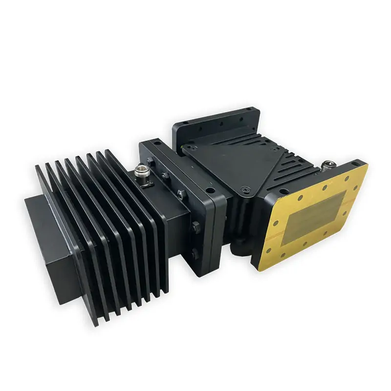
Microwave Isolator
For managing energy reflected toward the source.
View product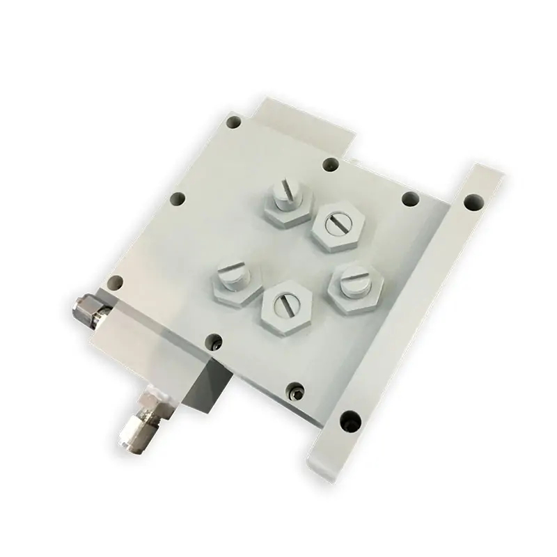
Microwave Water Load
For a waveguide termination that absorbs microwave power.
View product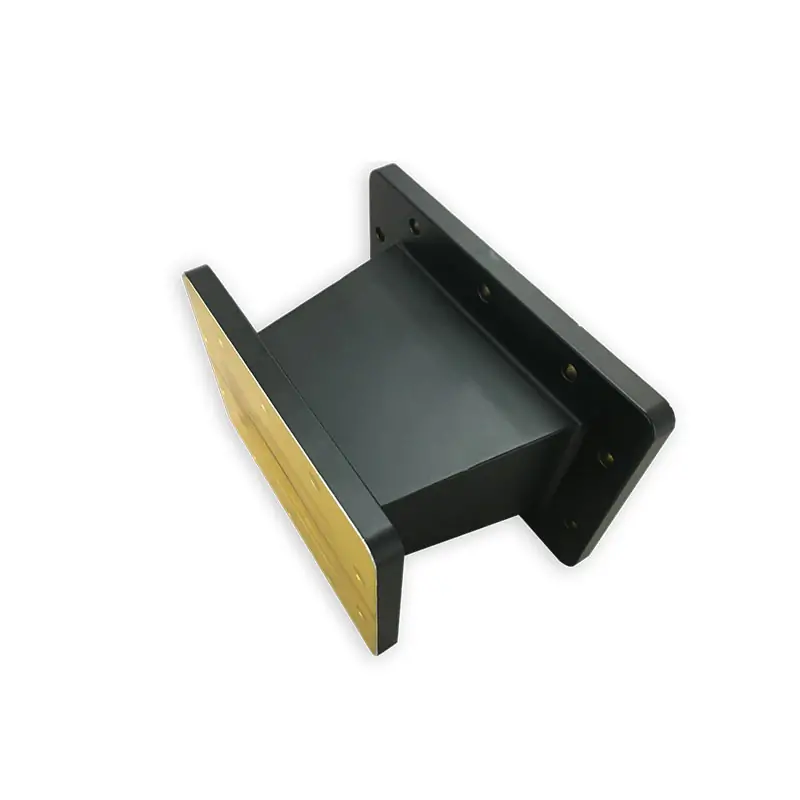
Microwave Transitions
For joining different waveguide interfaces.
View productHave a drawing or an existing part?
Send it with the details below. If some details are missing, tell us what you know and which points still need checking.
- Frequency and continuous power
- Required coupling and single/dual arrangement
- Connector type, gender and instrument input range
- Waveguide, flange and available length
Add the quantity, delivery destination and target date. Ask for the proposed configuration, drawing, price and lead time to be included in the quotation.
Email your requirements