
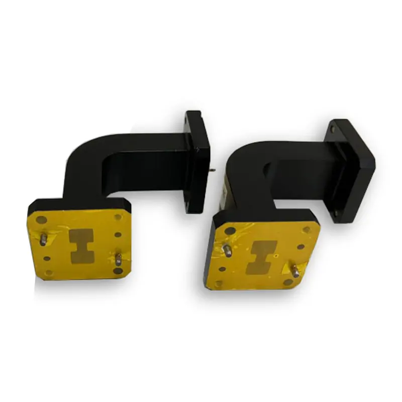
Waveguide Bends
Dolph Microwave double ridged waveguide bends are available for WRD84 to WRD180 waveguide systems, covering published model frequency ranges from 0.84 GHz to 40.0 GHz. The series includes E-plane and H-plane configurations, 45°, 60° and 90° bend options, cover or grooved flanges, and a maximum VSWR of 1.25.
Double Ridged Waveguide Bends
Double ridged waveguide bends are used when a WRD waveguide transmission path must change direction in the E-plane or H-plane. Model selection should be based on the required WRD interface, operating frequency range, bend direction, mechanical dimensions and flange configuration.
The published range covers WRD84 through WRD180, with individual model frequency ranges from 0.84 GHz to 40.0 GHz. Available configurations include 45°, 60° and 90° bends, cover or grooved flanges, and multiple standard length options.
Technical Specifications
Double Ridged Waveguide Bend Model Range
Several models have overlapping frequency ranges, so the required WRD interface must be confirmed in addition to the operating frequency.
How to Select a Double Ridged Waveguide Bend
Confirm the WRD Interface
Begin with the WRD interface used by the adjoining waveguide components. Frequency overlap alone does not make different WRD sizes interchangeable.
Select the Bend Plane
The ordering information uses WEB for an E-plane bend and WHB for an H-plane bend.
Define the Bend Angle
Published bend options include 45°, 60° and 90°. The required direction and orientation should be shown on the assembly drawing.
Confirm Length and Flange
Listed lengths include 45 mm, 60 mm, 90 mm, 100 mm or other lengths. Cover and grooved flange configurations are available.
Materials and Surface Finishes
The published specification table lists Al / Brass as the material options. The inside finish is listed as Iridite per MIL-C-5541, while the external body finish is listed as anticorrosion black painted.
The MIL-C-5541 reference applies specifically to the stated Iridite finish and should not be presented as a broader qualification claim for the complete product.
Part Number Guide
Published ordering example: DH-650DR WEB_WHB 50*50 P M A
Dolph Microwave
WRD650
E-Bend, default 90°
H-Bend, default 90°
A*B dimensions in millimetres
Flange cover
Flange grooved
Material Al
Technical Downloads
Review the product datasheet for the model range and ordering information. Use the flange document to check available double-ridge flange drawings and dimensions.
Frequently Asked Questions
What frequency range is covered by the listed models?
The published model ranges begin at 0.84-2.0 GHz for WRD84 and extend to 18.0-40.0 GHz for WRD180.
What is the published maximum VSWR?
The specification table lists a maximum VSWR of 1.25 for the published models.
Are E-plane and H-plane bends available?
Yes. The ordering information uses WEB for an E-plane bend and WHB for an H-plane bend.
Which bend angles are listed?
The published bend options are 45°, 60° and 90°. The ordering example identifies 90° as the default WEB and WHB configuration.
Which flange types are available?
The published options include cover and grooved flange configurations.
What should be included in an RFQ?
Include the operating frequency range, WRD type, E-plane or H-plane configuration, bend angle, A*B dimensions, required length, flange type, material and quantity.
Request a Double Ridged Waveguide Bend Quote
Include the following information in your RFQ:
- Operating frequency range
- Required WRD waveguide type
- E-plane or H-plane configuration
- Required bend angle
- Required A*B dimensions
- Required length
- Cover or grooved flange
- Al or brass material
- Required quantity
- Mechanical drawing, where available







