June 2026

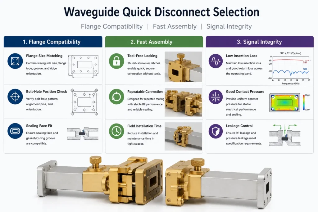
Waveguide Quick Disconnect Selection | Compatibility, Assembly, Signal Integrity

Select a waveguide quick disconnect by its exact mating interface, locking arrangement and verified RF performance after reconnection. For a pressurized line, add separate pressure and leakage limits. A fast latch does not establish flange compatibility, low insertion loss or a gas-tight seal. Selection gate Evidence to request Compatible interface Dimensioned aperture, flange, locating features, […]

Waveguide Quick Disconnect Selection | Compatibility, Assembly, Signal Integrity Read More »
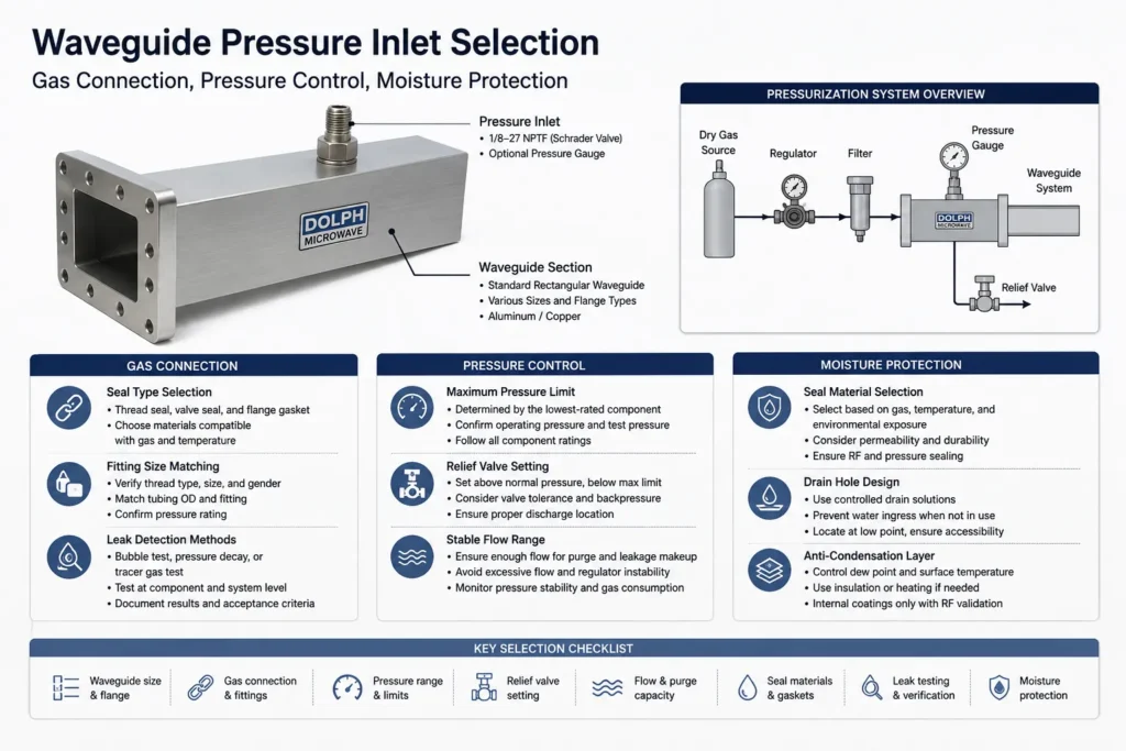
Waveguide Pressure Inlet Selection | Gas Connection, Pressure Control, Moisture Protection

Choose a waveguide pressure inlet by the waveguide and flange drawing, exact gas connection, complete assembly pressure limit and required gas dryness. Then size the supply and protection system for purging, leakage makeup and credible regulator failure. The inlet’s catalog pressure is not automatically the operating setpoint for the line. Use clean, dry air or

Waveguide Pressure Inlet Selection | Gas Connection, Pressure Control, Moisture Protection Read More »

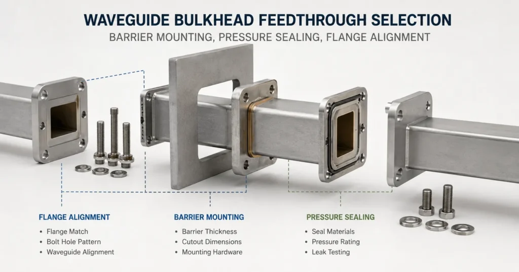
Waveguide Bulkhead Feedthrough Selection | Barrier Mounting, Pressure Sealing, Flange Alignment

Select a waveguide bulkhead feedthrough by the finished wall stack, mounting cutout, mating flange drawings and required sealing boundary. Then verify mechanical fit, RF performance and any pressure or leakage requirement in the installed configuration. A bulkhead feedthrough carries the waveguide through a wall or panel. An open RF bore does not separate the gas

Waveguide Bulkhead Feedthrough Selection | Barrier Mounting, Pressure Sealing, Flange Alignment Read More »

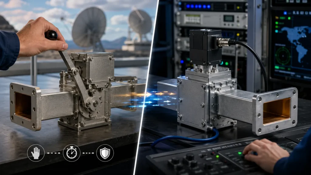
Manual vs Electric Waveguide Switches | Control, Speed, Reliability

Choose a manual waveguide switch for occasional, accessible changes. Choose an electric switch when the RF path must change remotely, automatically or within a measured time limit. Neither actuation method guarantees lower loss or longer life. Compare the actual RF specifications, switching conditions, feedback and endurance test for the selected model. Requirement Selection consequence Infrequent

Manual vs Electric Waveguide Switches | Control, Speed, Reliability Read More »

Waveguide Power Handling | Continuous Wave Power and Peak Power, Breakdown Limits, Cooling

Waveguide power handling is limited by both heating and electrical breakdown. Check the continuous or average power, pulse peak power, operating frequency, gas pressure and cooling conditions separately. A low duty cycle reduces average power; it does not prove that the waveguide can withstand the pulse peak. The calculations below are illustrative engineering examples, not

Waveguide Power Handling | Continuous Wave Power and Peak Power, Breakdown Limits, Cooling Read More »

Waveguide Frequency Bands Chart | WR Sizes, Cutoff Frequency, Applications

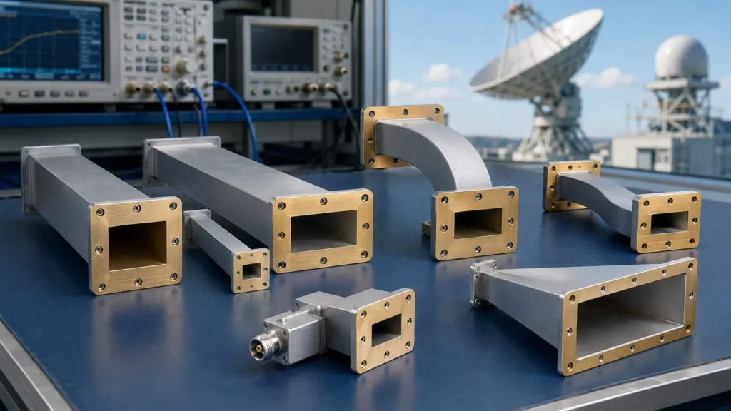
Use the chart below to shortlist a WR size whose specified operating band covers your full frequency range. Then check the actual component’s flange, insertion loss, return loss, peak and average power, and environmental limits. Being above cutoff does not establish acceptable performance. WR Sizes WR Designation Meaning WR identifies rectangular waveguide. Its number approximately

Waveguide Frequency Bands Chart | WR Sizes, Cutoff Frequency, Applications Read More »

Waveguide Flange Size Guide | EIA Standard, IEC Types, Gasket Fit

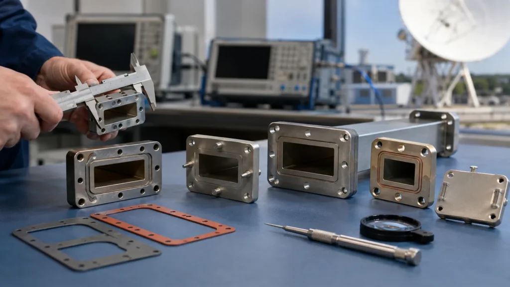
Choose a waveguide flange by its complete interface drawing, not the WR size alone. Match the RF aperture, bolt and alignment-hole pattern, mating face, gasket groove and fasteners. Two parts marked WR90 can carry the same waveguide size yet require different flange interfaces. IEC 60154-2 covers mechanical dimensions and compatibility for ordinary rectangular waveguide flanges.

Waveguide Flange Size Guide | EIA Standard, IEC Types, Gasket Fit Read More »

Scroll to Top
Blank Form (#3)