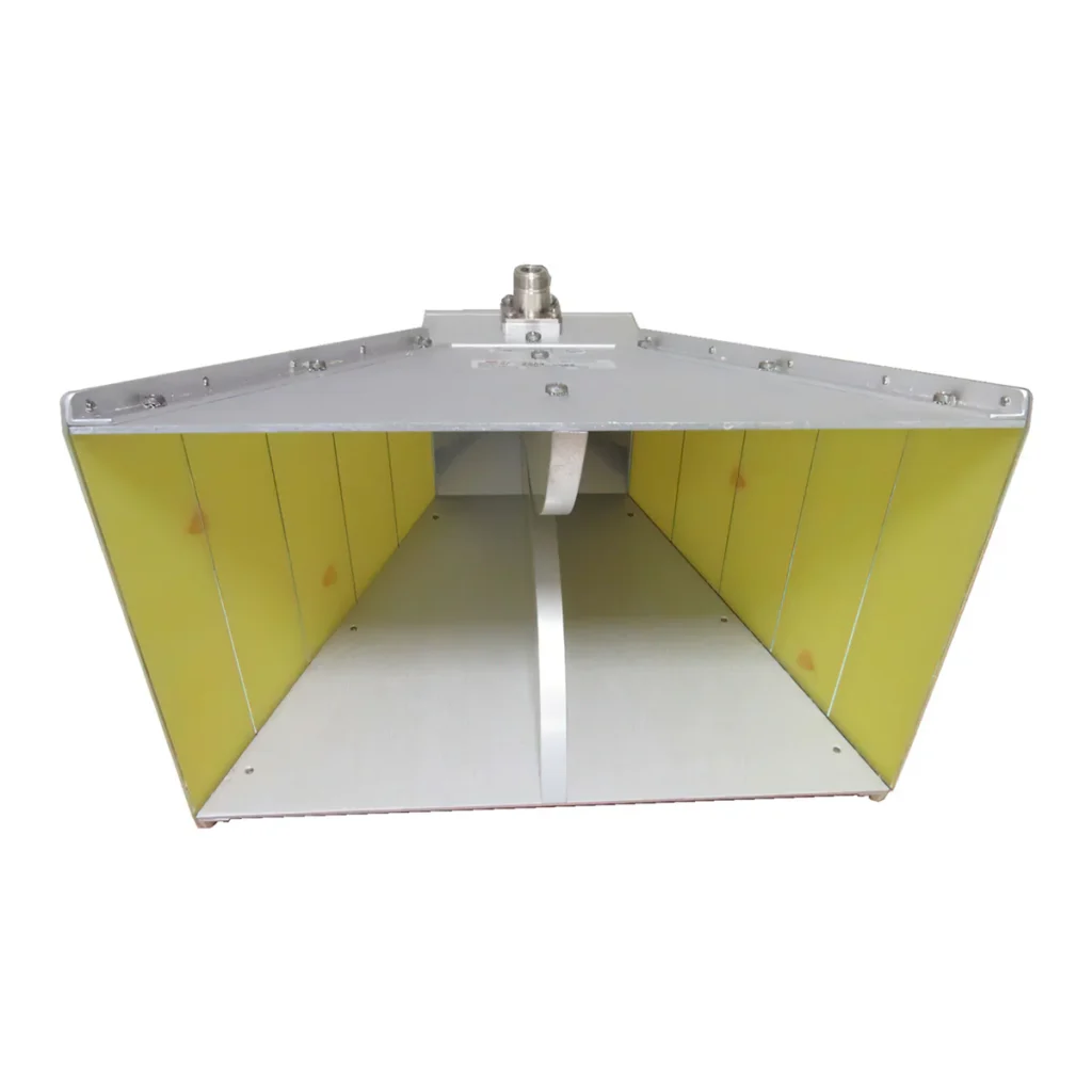
Horn Antenna Gain Calculation Guide | Formula, Aperture Area, Efficiency
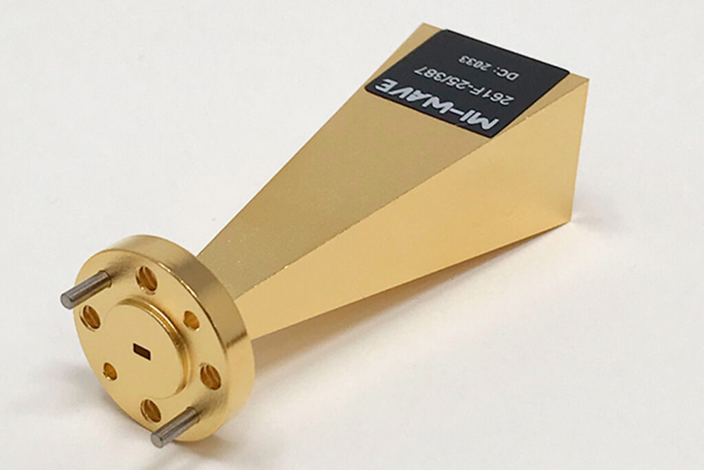
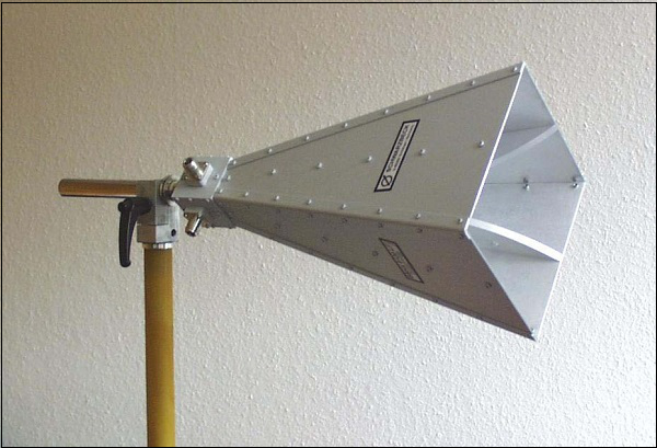
Horn antenna gain is determined by the aperture area, operating wavelength, and efficiency (typically taken as 0.6). The calculation formula is: 4π multiplied by the area multiplied by the efficiency, divided by the square of the wavelength. A larger aperture area or a shorter wavelength results in higher gain, which significantly enhances the directional transmission […]
Horn Antenna Gain Calculation Guide | Formula, Aperture Area, Efficiency Read More »