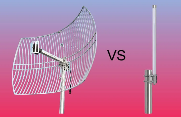
What is the difference between Yagi and Omni antenna
Yagi antennas are directional, with a driven element, reflector, and directors, offering 10–15dBi gain at 2.4GHz for focused point-to-point links. Omni antennas radiate uniformly horizontally (2–5dBi gain), suited for area coverage; Yagi typically operates 400MHz–6GHz, Omni 30MHz–6GHz, differing in pattern and use case. How They Send and Receive Signals A Yagi antenna, like a flashlight, […]
What is the difference between Yagi and Omni antenna Read More »