A flat-panel satellite antenna steers its beam across a low-profile aperture. Phased arrays and tunable metasurfaces can both do this electronically, but they use different RF architectures. For LEO service, select the terminal by network compatibility, EIRP and G/T across its scan range, tracking performance, and available electrical power—not by panel thickness alone.
Metamaterials and phased arrays: what changes inside the panel
“Flat panel” describes the shape. It does not identify the beam-steering technology or guarantee Ku-band, Ka-band, or multi-orbit operation.
Active phased array. Controls the signals feeding antenna elements or subarrays; amplification is distributed across the aperture. Check transmit power, receive noise, scan loss, cooling, and the number of independently usable beams.
Tunable metasurface. Changes the response of small radiating elements coupled to a feed structure. Check tuning range, efficiency, bandwidth, temperature response, and measured radiation patterns.
Mechanically steered or hybrid panel. Moves the panel, uses electronic steering, or combines both methods. Check moving clearances, tracking limits, cable routing, and maintenance access.
A waveguide-fed metasurface can steer by changing individual elements’ resonance rather than fitting every element with a conventional phase shifter and amplifier. The published analysis by Smith and colleagues describes this specific architecture; it does not make every flat panel a metamaterial antenna.[1]
Liquid crystals are one tuning approach. Varactor-tuned elements have also been demonstrated in an electronically steered metasurface prototype. Neither approach establishes a universal switching time, terminal power draw, or service life.[2]
Separate the antenna from the complete terminal when comparing size and power. A quoted panel measurement may exclude the modem, RF electronics, power supply, mounting frame, heater, or radome. Ask for the installed envelope and total mass, including those items.
Electronic steering: scan range is not constant performance
A phased array changes the relative phase of signals across its aperture so they add in the selected direction. For a simple linear array, the steering phase increment has magnitude 2π(d/λ) sin θ, where d is element spacing and θ is measured from broadside. With half-wavelength spacing, steering to 30° requires a 90° increment; a 6-bit phase shifter’s 5.625° step is its resolution, not the required steering increment.[3]
A panel pointed away from broadside presents less projected area to the satellite. In a simple projection-only model, Aprojected = A cos θ: the corresponding reduction is about 1.5 dB at 45° and 3.0 dB at 60°. These are geometric examples, not guaranteed antenna scan losses. Element patterns, coupling, mismatch, polarization, and radome losses change the measured result.
For a level horizontal panel, a 60° scan angle from broadside corresponds to a satellite elevation of 30°. Vehicle roll or pitch changes that relationship. A claim of “360° azimuth coverage” does not mean the terminal has useful gain everywhere down to the horizon.
Require EIRP and G/T plots against scan angle at the transmit and receive band edges. EIRP combines RF power and transmit gain; G/T combines receive gain and system noise temperature. A single broadside gain figure cannot show whether the link works at its lowest operating elevation.
Increasing receiver gain amplifies both the received signal and noise. A low-noise amplifier limits the extra noise introduced by later receiver stages; it does not recover signal-to-noise ratio already lost through blockage, poor pointing, or propagation loss.
Table of Contents
Measure steering, acquisition, and handover separately
- Beam update time: how quickly the antenna applies a new pointing command.
- Acquisition time: how long a terminal takes to locate a usable signal, synchronize, and enter service.
- Handover interruption: how long user traffic stops when the network changes satellite or beam.
- Recovery time: how long service takes to return after a defined obstruction or loss of lock.
A fast phase shifter does not guarantee a fast network handover. The modem, synchronization process, network scheduler, and authentication state also affect the interruption. Specify cold-start and warm-start conditions, then measure packet loss and interruption during actual satellite transitions.
Make-before-break operation requires overlapping usable links and terminal/network support. Two simultaneous beams are a feature to verify, not a property of every flat panel. Ask for per-beam EIRP and G/T: splitting the aperture or sharing transmitter power can reduce the margin available to each link.
LEO tracking: what the short orbit changes
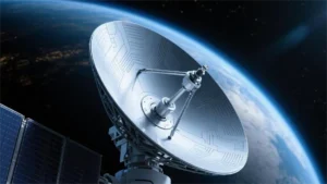
LEO satellites move across the sky instead of staying over one apparent position like a geostationary satellite. ESA gives approximately 7.8 km/s and a roughly 90-minute orbit as representative low-orbit figures. Actual speed, period, and visible pass duration depend on altitude and geometry.[4]
The antenna controller needs terminal position and satellite pointing information. A moving platform also needs its orientation accounted for. The required control update rate depends on beamwidth, platform rotation, satellite angular motion, and permitted pointing loss; one fixed update rate cannot cover every aircraft, ship, and ground terminal.
A flat panel is one way to follow this motion. A mechanically tracking LEO/MEO antenna is another system architecture. Compare tracking envelope, gain, obstruction clearance, and installation space for the same link requirement.
Keep propagation delay separate from internet latency
For an illustrative 550 km satellite directly overhead, one ground-to-satellite vacuum path takes about 1.83 ms: distance divided by 299,792 km/s. Two such legs total 3.67 ms, before processing. A user-to-satellite-to-gateway path and its return would involve four legs, about 7.34 ms in the simplified equal-distance geometry. Real slant paths are longer.
Internet round-trip time also includes gateway location, terrestrial routing, inter-satellite links where used, processing, and queues. “20–50 ms” can only describe a specified network measurement or service claim; it is not a physical constant for LEO and does not guarantee a faster route than fiber.
Doppler shift depends on radial velocity, not total orbital speed alone: |Δf| ≈ f|vr|/c. At 14 GHz, an assumed radial speed of 7.5 km/s gives about 350 kHz. This calculated example helps size a frequency-tracking requirement; it is not the shift throughout a satellite pass.
Antenna compatibility also requires the right transmit and receive sub-bands, polarization, waveform/modem support, and operator approval. “Ku/Ka capable” does not establish compatibility with any named constellation. Network authorization and RF capability are separate requirements.
Power, heat, weather, and interference
Compare complete-terminal DC input under the same operating conditions: receive/search mode, sustained transmission, peak demand, and cold-weather heating. State RF output power, ambient temperature, scan angle, and traffic load alongside the electrical measurement.
For example, an assumed 150 W terminal requires an ideal 3.13 A at 48 V, or 12.5 A at 12 V, before conversion and cable losses. Over 8 hours it uses 1.2 kWh. These are sizing calculations, not specifications for a Dolph product; the power supply must also meet the selected terminal’s startup and peak requirements.
Request operating temperature limits together with thermal derating curves. A survival temperature does not promise full transmit performance at that temperature. Verify cooling clearance and whether a sun-heated mounting surface changes the installation limit.
Rain attenuation depends on frequency, polarization, rainfall statistics, elevation, and path geometry. A statement such as “50 mm/h rain causes 10 dB loss” is incomplete without the path conditions. ITU-R P.618 provides Earth-space propagation prediction methods for a site-specific link budget.[5] The Ku-band antenna selection guide explains how aperture and fade margin affect that budget.
For outdoor installations, ask which ingress, vibration, corrosion, and temperature tests were performed, with their conditions and acceptance criteria. An IP rating does not establish salt-spray resistance or aviation qualification. Accelerated UV exposure does not, by itself, prove a fixed number of years outdoors.
Check measured co-polar and cross-polar radiation patterns across frequency and scan angle. Sidelobe level relative to the main beam is expressed in dB; dBc/Hz describes a spectral density ratio and is not the same measurement.
ITU-R S.1503 describes the software methodology used to assess non-GSO fixed-satellite systems against applicable Article 22 equivalent power-flux-density limits. It is not a universal sidelobe specification or one fixed ground-level power limit for every terminal.[6] Obtain the operator’s acceptance criteria and the authorization applicable to the intended band, service, and location.
What to put in the selection and acceptance specification
| Requirement | Evidence to request |
|---|---|
| Network and RF compatibility | Operator approval, Tx/Rx frequency limits, polarization, modem/interface requirements, and permitted operating regions. |
| Usable scan coverage | EIRP and G/T versus angle and frequency, including the minimum elevation and expected platform tilt. |
| Traffic continuity | Cold/warm acquisition tests, handover packet loss, interruption duration, and recovery after a defined blockage. |
| Power and cooling | Complete-terminal steady and peak DC draw, heater demand, supply limits, cooling clearance, and thermal derating. |
| Mechanical integration | Installed dimensions and mass, mounting loads, radome clearance, connector orientation, and cable bend requirements. |
| RF acceptance | Radiation patterns, polarization performance, emissions evidence, and measured results for the supplied configuration. |
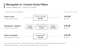
For a system using separate RF feed components, include the antenna feeder network losses and interfaces in the same link budget. Match the waveguide size and flange drawing, then specify the operating band, CW/peak power, return loss, insertion loss, and environmental conditions at each interface.
Define the RF interfaces before ordering components
Send Dolph your Tx/Rx bands, interface drawings, power levels, and loss budget so the required waveguide or feed-network configuration can be checked.
Choose the panel that meets the link budget at the hardest operating angle and temperature. Confirm the network, measure handover interruption, and size the power supply for the complete terminal. A thinner enclosure or faster beam command alone cannot establish those results.