+86 29 8881 0979

default

6 Key Points on the Phase Difference in Directional Couplers

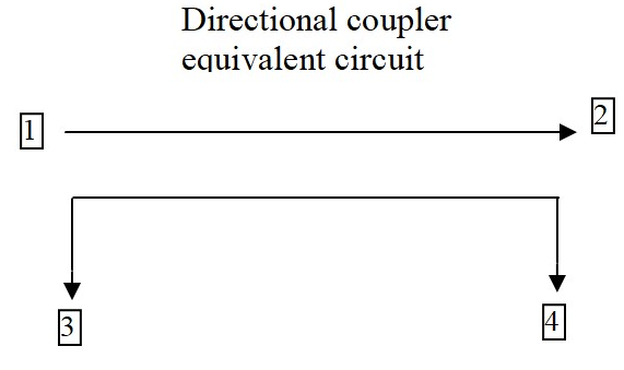
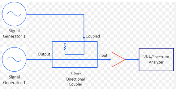
The phase difference between the coupled and mainline signals is critical, typically targeting 90° for ideal quadrature operation. This shift is frequency-dependent and is measured using a vector network analyzer, which precisely quantifies the phase deviation (e.g., ±5°) from the theoretical value across the specified bandwidth, such as 1-2 GHz. What is Phase Difference? In […]

6 Key Points on the Phase Difference in Directional Couplers Read More »

6 key points about ideal directional coupler directivity

Ideal directional coupler directivity exceeds 30dB (40dB for precision models), requires precise λ/4 spacing (±0.01mm tolerance), depends on port matching (VSWR <1.05), improves with ferrite loading (2-18GHz range), degrades <0.5dB after 10^9 cycles, and needs -55dB isolation at 1GHz for optimal forward/reflected wave separation. What Directivity Means Directional coupler directivity is one of the most

6 key points about ideal directional coupler directivity Read More »

6 specific points to explain the coupling ratio of a directional coupler

The coupling ratio of a directional coupler is determined by the gap spacing (0.1-1mm for 3-30dB coupling), conductor geometry (edge-coupled lines yield 6-20dB), substrate permittivity (εᵣ=2.2-10.8 affects coupling ±3dB), frequency (varies ±1dB across 2-18GHz), manufacturing tolerance (±0.5dB for precision CNC-machined units), and load matching (VSWR>2.0 can degrade ratio by 2dB). What Coupling Ratio Means The

6 specific points to explain the coupling ratio of a directional coupler Read More »

Top 6 Global Suppliers of Waveguide Horn Antennas for High-Performance of 2024

In 2024, the top waveguide horn antenna suppliers include ​​Millimeter Wave Products Inc.​​ (up to 325 GHz), ​​Pasternack​​ (custom designs <1.5:1 VSWR), ​​Flann Microwave​​ (precision-machined up to 110 GHz), ​​RFspin​​ (low-loss <0.1 dB), ​​A-Info​​ (broadband 18-220 GHz), and ​​Fairview Microwave​​ (ISO 9001-certified, 10-40 dB gain). Key Players in Waveguide Horns Waveguide horn antennas are critical

Top 6 Global Suppliers of Waveguide Horn Antennas for High-Performance of 2024 Read More »

5 differences between rectangular and circular waveguide

Rectangular waveguides (e.g., WR-90) support ​​TE10 dominant mode​​ at ​​8.2–12.4GHz​​ with ​​0.1dB/m loss​​, while circular waveguides handle ​​TE11 mode​​ but suffer ​​higher attenuation (0.3dB/m)​​. Rectangular types offer ​​30% wider bandwidth​​, whereas circular variants enable ​​polarization rotation​​. Machining tolerances are stricter for circular guides (​​±0.0005″ vs. ±0.001″​​), and rectangular flanges ​​resist misalignment​​ better due to ​​keyed

5 differences between rectangular and circular waveguide Read More »

6 Key Points About Dimensions A and B in rectangular waveguide

In rectangular waveguides (e.g., WR-90), ​​dimension A (0.9″)​​ determines the ​​cutoff frequency (6.56GHz for TE10)​​, while ​​B (0.4″)​​ affects ​​higher-mode suppression​​ (TE20 starts at 13.1GHz). The ​​A/B ratio (2.25:1)​​ optimizes ​​single-mode bandwidth (8.2–12.4GHz)​​ with ​​0.1dB/m loss​​. ​​Tolerances (±0.001″)​​ must avoid ​​VSWR >1.2​​, and ​​A > λ/2​​ prevents ​​evanescent wave decay​​. ​​B < A/2​​ minimizes ​​TM11

6 Key Points About Dimensions A and B in rectangular waveguide Read More »

5 reasons why a waveguide is round

Circular waveguides minimize ​​surface current loss​​ (0.05dB/m vs. 0.1dB/m in rectangular) due to ​​uniform field distribution​​. They support ​​TE11/TM01 modes​​ for ​​polarization flexibility​​ and handle ​​higher power (10kW vs. 5kW)​​ with ​​360° symmetric heat dissipation​​. Their ​​lack of sharp edges​​ reduces ​​voltage breakdown risks​​ (>50kV/cm), and ​​tolerance to rotational misalignment​​ (±5°) makes them ideal for

5 reasons why a waveguide is round Read More »

5 differences between directional couplers and taps

Directional couplers ​​sample signals bidirectionally​​ (e.g., 20dB coupling ±0.5dB) with ​​40dB directivity​​, while taps ​​extract signals unidirectionally​​ (e.g., 10dB fixed loss). Couplers handle ​​wide bandwidths​​ (2–18GHz) versus taps’ ​​narrowband operation​​ (±5% of center frequency). ​​Insertion loss​​ is lower in couplers (<0.3dB vs. >3dB for taps), and couplers ​​preserve impedance matching​​ (VSWR <1.2), whereas taps often

5 differences between directional couplers and taps Read More »

Scroll to Top
Blank Form (#3)