+86 29 8881 0979

default

How to design an antenna for a specific frequency

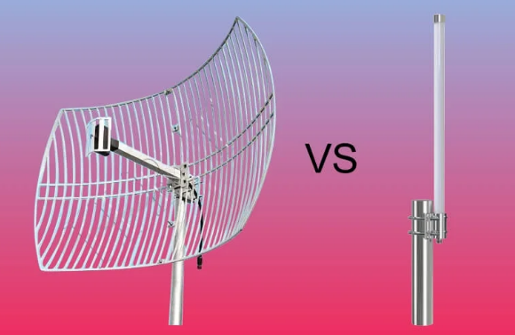
Design an antenna for a specific frequency (e.g., 2.4GHz) by calculating length via f=2Lc​ (≈6.25cm for dipole), adjusting for dielectric (FR4 εr​≈4.3) to shorten, and matching impedance to 50Ω via feed point or transformer for efficient radiation. Choose Your Target Frequency For instance, a Wi-Fi router operating at 2.4 GHz has a fundamentally different antenna […]

How to design an antenna for a specific frequency Read More »

What is the difference between Yagi and Omni antenna

Yagi antennas are directional, with a driven element, reflector, and directors, offering 10–15dBi gain at 2.4GHz for focused point-to-point links. Omni antennas radiate uniformly horizontally (2–5dBi gain), suited for area coverage; Yagi typically operates 400MHz–6GHz, Omni 30MHz–6GHz, differing in pattern and use case. How They Send and Receive Signals A Yagi antenna, like a flashlight,

What is the difference between Yagi and Omni antenna Read More »

What is the material of a directional coupler

Directional couplers commonly use brass (copper-zinc alloy, 60–70% Cu) for housings for conductivity, PTFE (εr≈2.1, tanδ<0.001) for high-frequency PCB substrates, or ceramic (Al₂O₃, εr≈9.8) for power handling, balancing loss and thermal stability. Common Materials Used A 1 dB increase in insertion loss can degrade system performance by 20%, making low-loss materials non-negotiable for high-frequency applications.

What is the material of a directional coupler Read More »

What is the function of coupler antenna

Coupler antennas integrate signal routing and isolation functions, enabling power division (e.g., 10–20dB splits) or sampling (insertion loss <0.3dB) between transmit/receive paths while maintaining >25dB isolation at 2–18GHz to minimize interference, optimizing RF system efficiency. Connecting Two Devices Wirelessly A common challenge in RF systems is efficiently transferring a signal from a primary transmitter to

What is the function of coupler antenna Read More »

What are the different types of cable ends

Cable ends include crimped (with 5-15N pull-off force for 18-22AWG wires, common in automotive vibrations), soldered (300-400°C soldering iron, <0.1mΩ contact resistance for precision electronics), insulation displacement (IDC, piercing 22-10AWG insulation without stripping, 10Gbps data transmission), and threaded (M3-M6 terminals, 0.5-2N·m torque for industrial equipment, vibration-resistant). USB Types and Uses USB connectors are one of

What are the different types of cable ends Read More »

What is the limit of C-Band

The C-band, defined by ITU as 4-8 GHz, faces practical limits: rain fade at 100mm/h induces 0.5-1dB/km loss at 6GHz, impacting satellite links (uplink 5.925-6.425GHz, downlink 4.6-5.0GHz). Antenna gain (30-40 dBi for 3-6m dishes) and LNA noise figures (0.5-1.5dB) constrain sensitivity, while physical size limits high-gain use in compact systems. Defining C-Band Frequency Range The

What is the limit of C-Band Read More »

How do satellite antennas work

Satellite antennas operate via parabolic reflectors that focus electromagnetic waves onto a feed horn; a 3-meter diameter dish in Ku-band (12-18GHz) achieves ~40dBi gain, directing signals toward satellites. During transmission, electrical signals convert to waves at the feed, reflected into parallel beams by the parabola; reception reverses this, focusing incoming waves (error <0.1° in azimuth/elevation)

How do satellite antennas work Read More »

How do you test a directional coupler

To test a directional coupler, connect it to a signal generator (output: +10dBm, 2-4GHz) and spectrum analyzer. Measure input power (Pin) at the main port, coupled power (Pcouple) at the coupled port, and isolated port power (Piso). Calculate insertion loss (Pin-Pthru, typical 0.5-2dB), isolation (Pin-Piso ≥20dB), and directivity (Pcouple-Piso ≥30dB) to validate performance. Measure Insertion

How do you test a directional coupler Read More »

What are the factors contributing to the loss inside a wr187 waveguide

Losses in WR187 waveguides (8.2-12.4GHz, a=47.55mm, b=23.78mm) stem from conductor surface roughness (Ra>0.5μm adds 0.1-0.3dB/cm), dielectric oxidation (tanδ=1e-4 vs. 1e-6 clean, +0.02-0.05dB/cm), mode conversion at misaligned flanges (>λ/100, λ≈30mm at 10GHz, +0.1-0.3dB), and scattering from scratches (>λ/20, +0.05-0.15dB/cm). Wall Material Conductivity Impact The conductivity of the wall material is a primary factor in determining the

What are the factors contributing to the loss inside a wr187 waveguide Read More »

What is the beamwidth of quad-ridged horn antenna

A quad-ridged horn antenna typically has a beamwidth of 60-80° in X-band (8-12 GHz), varying with ridge spacing and length; lower bands (e.g., L-band) may reach 90-100°, while higher Ku-band narrows to 50-60°, ideal for satellite communication directional coverage. Basic Antenna Beamwidth Explanation​​ Antenna beamwidth, specifically the ​​Half-Power Beamwidth (HPBW)​​, is the most critical metric

What is the beamwidth of quad-ridged horn antenna Read More »

Scroll to Top
Blank Form (#3)