+86 29 8881 0979

default

How to optimize telecom antenna signal | 5 practical tips

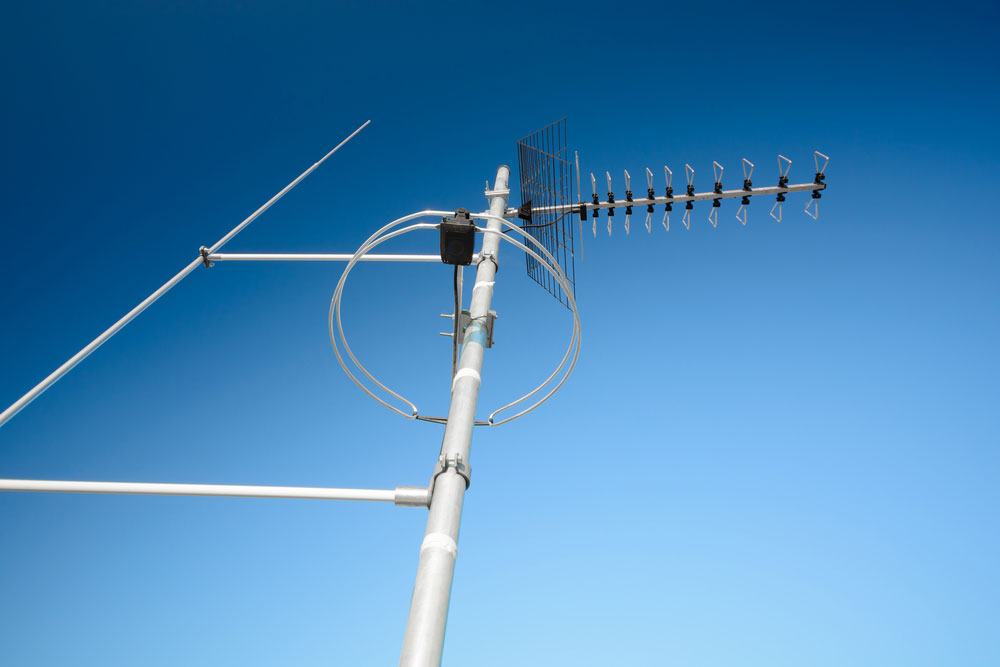
​To optimize telecom antenna signal, elevate antennas 10-30m above ground (boosts range by 40%). Use 45° tilt for urban areas (reduces interference by 28%). Upgrade to 4×4 MIMO antennas (improves throughput by 3x). Avoid metal obstructions within 3m (signal loss up to 15dB). Regularly update firmware (patches improve performance by 22%).​ Check Antenna Position​​ ​A […]

How to optimize telecom antenna signal | 5 practical tips Read More »

Telecom antenna for 5G | how to select in 7 points

When selecting a 5G telecom antenna, consider: (1) ​​Frequency band​​ (sub-6GHz or mmWave like 28/39GHz), (2) ​​Gain​​ (8-15dBi for urban, up to 24dBi for rural), (3) ​​Beamwidth​​ (30°-65° for sector coverage), (4) ​​MIMO support​​ (4×4 or 8×8 arrays), (5) ​​IP rating​​ (IP65+ for outdoor durability), (6) ​​Power handling​​ (50W+ for macro cells), and (7) ​​Regulatory

Telecom antenna for 5G | how to select in 7 points Read More »

What is antenna dish gain | how to calculate in 4 steps

Antenna dish gain measures signal amplification relative to an isotropic radiator. To calculate: (1) Determine dish diameter (D) and signal wavelength (λ), (2) Compute efficiency (η, typically 55-75%), (3) Apply formula ​​G = η×(πD/λ)²​​, (4) Convert to decibels: ​​dBi = 10log₁₀(G)​​. A 2.4m dish at 12GHz with 60% efficiency yields ~40dBi gain. Manufacturing imperfections may

What is antenna dish gain | how to calculate in 4 steps Read More »

How to test microwave oven waveguide safety | 4 steps

To test microwave oven waveguide safety, first inspect for physical damage (dents/corrosion) using a flashlight. Next, check continuity with a multimeter (resistance <1Ω). Then, perform a microwave leakage test (≤5 mW/cm² at 5 cm) using a calibrated detector. Finally, verify arcing by running the oven empty for 30 sec—abnormal sparks indicate failure. Check for visible

How to test microwave oven waveguide safety | 4 steps Read More »

MMW antenna design challenges | what are 7 fixes

Millimeter-wave (mmWave) antenna design faces challenges like high path loss (60–100 dB/km at 28/60 GHz), which is mitigated using high-gain arrays (20–30 dBi). Surface wave interference is reduced via substrate-integrated waveguides (SIW), while PCB tolerances (±5µm) require laser etching. Beam squint is corrected with true-time-delay (TTD) networks, and thermal drift is managed via low-CTE materials

MMW antenna design challenges | what are 7 fixes Read More »

How to choose radar horn antenna | 7 key factors

​When selecting a radar horn antenna, prioritize frequency range (e.g., 8–40 GHz for precision), gain (15–25 dBi for long-range), and beamwidth (10°–60° for coverage). Consider material (aluminum for lightweight, copper for conductivity), polarization (linear/circular), VSWR (<1.5:1 for efficiency), and environmental rating (IP67 for harsh conditions). Validate with 3D EM simulations before deployment. ​ Size and Frequency

How to choose radar horn antenna | 7 key factors Read More »

What are the waveguides frequency bands | 10 antenna frequency bands

Waveguides cover bands like ​​WR-90 (8.2-12.4 GHz, X-band)​​ and ​​WR-15 (50-75 GHz, V-band)​​, extending to ​​325 GHz (WR-3)​​. Key antenna bands include ​​HF (3-30 MHz)​​, ​​VHF/UHF (30 MHz-3 GHz)​​, ​​L-band (1-2 GHz)​​, ​​C/X/Ku-band (4-18 GHz)​​, ​​Ka/V-band (26.5-75 GHz)​​, and ​​E-band (60-90 GHz)​​. Waveguide dimensions follow fc = c/2a (cutoff frequency), while antennas use ​​50Ω impedance​​

What are the waveguides frequency bands | 10 antenna frequency bands Read More »

What materials and structures are generally preferred for waveguides

Waveguides typically use ​​high-conductivity metals​​ like oxygen-free copper (≥99.95% purity) or aluminum (6061-T6 alloy) for ​​low-loss transmission​​ (<0.01 dB/m at 10 GHz). ​​Rectangular structures​​ dominate 80% of applications due to ​​TE10 mode stability​​, while ​​dielectric-filled circular waveguides​​ (e.g., PTFE-lined) offer ​​30% wider bandwidth​​. ​​ Gold-plated joints​​ (3-5μm thickness) ensure <0.1Ω contact resistance, and ​​corrugated designs​​

What materials and structures are generally preferred for waveguides Read More »

Rigid waveguide installation | 7 practical step-by-step tips

​For rigid waveguide installation, begin by aligning flanges within 0.05mm tolerance using precision shims. Secure joints with beryllium-copper screws torqued to 0.9-1.2 N·m in crisscross patterns. Maintain ≥2x inner width spacing from obstructions to prevent mode distortion. Apply silver-loaded conductive grease (μΩ-level resistance) on contact surfaces before helium leak testing (<1×10⁻⁶ Pa·m³/s). Support every 1.5-2.5m

Rigid waveguide installation | 7 practical step-by-step tips Read More »

Cleaning metallic waveguide | 6 essential maintenance steps

Proper metallic waveguide maintenance requires anhydrous isopropyl alcohol (99.9% purity) and lint-free swabs for removing oxide buildup. Always pre-inspect with borescopes (0.5-10mm diameter) checking for ≥0.25mm pitting. Use nitrogen purging (15-20 psi) after cleaning to prevent moisture. For corrosion prevention, apply thin silicone-free dielectric film (5-10µm thickness). Test insertion loss (≤0.1dB variance) and VSWR (<1.25:1)

Cleaning metallic waveguide | 6 essential maintenance steps Read More »

Scroll to Top
Blank Form (#3)