RF rotary joints transmit RF signals during rotation using sliding gold-plated contacts (12-24 channels) or capacitive coupling, maintaining <0.5dB insertion loss from DC-60GHz, enabling 360° movement in radar/communication systems without signal degradation.
Table of Contents
Basic Working Principle
An RF rotary joint, often called a slip ring, is a precision electromechanical device that enables the continuous transmission of radio frequency (RF) signals between a stationary structure and a rotating platform. Think of a radar system on a naval ship: the antenna atop the mast rotates 360 degrees at speeds of up to 15-20 RPM, while the sensitive electronics generating the high-power signal are safely housed below deck. The rotary joint is the critical, often overlooked, component in the mast’s base that makes this seamless movement possible. Its core function is to maintain a stable 50-ohm impedance connection to prevent signal reflections that can degrade performance, all while handling power levels from a few watts in data links to several megawatts in long-range search radars.
At its heart are two main parts: a stationary outer conductor and a precisely machined inner rotor. The challenge is maintaining electrical continuity between these moving parts without a fixed physical connection like a cable, which would twist and break. This is solved with a micrometer-scale gap and specialized interfaces. The critical interface often uses spring-loaded contacts, typically made of beryllium copper or precious metals like gold plating >1.5 microns thick, which press against a smooth, hardened sliding surface on the rotor. This creates a low-resistance electrical path. For higher-frequency signals (>18 GHz), the design shifts to waveguide technology, using precisely aligned choke joints that function as a low-loss RF hinge, leveraging electromagnetic field theory to guide the wave across the air gap between the stationary and rotating sections with minimal loss (typically <0.3 dB).
The ultimate design goal is to minimize three key parameters: Insertion Loss (<0.5 dB is excellent), Voltage Standing Wave Ratio or VSWR (<1.25:1 is ideal), and phase variation (<1 degree of wiggle).
The performance is quantified by its Insertion Loss, often specified at <0.3 dB, meaning over 99% of the signal power is successfully transmitted through the joint. VSWR, a measure of signal reflection, is typically maintained at <1.5:1 across the entire specified frequency band, such as 2-18 GHz. The lifetime is measured in millions of rotations, with modern designs often rated for 100+ million cycles before maintenance is needed, assuming operation within specified axial and radial load limits (e.g., <50 N axial, <20 N radial) and in a controlled environment. This reliability is why they are indispensable in systems like CT scanners, where continuous gantry rotation is required for clear imaging, and in wind turbines for transmitting data from pitch and yaw sensors.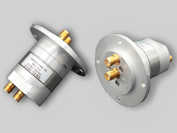
Key Parts Inside
Each component is meticulously designed to manage the conflicting demands of continuous rotation and stable, high-frequency signal transmission. The performance of a joint rated for 18 GHz with a VSWR < 1.25:1 and a service life exceeding 200 million rotations is directly dictated by the materials, tolerances, and assembly of these internal parts. Understanding these components is crucial for selecting the right joint for an application, whether it’s for a low-power 5W satellite communication antenna or a high-power 50 kW naval radar system.
The foundation is the housing (or stator), typically machined from aluminum 6061-T6 or stainless steel, which provides structural integrity and shields the internal components from external EMI. Inside, the rotor forms the center conductor of the coaxial line. It’s often made from beryllium copper or phosphor bronze for its excellent spring properties and electrical conductivity, and is precision-ground to a diameter with tolerances as tight as ±5 microns (.005 mm). The most critical interface is the electrical contact system. For coaxial types, this involves multiple finger stocks (or spring contacts). A single joint may contain 12 to 24 individual beryllium copper fingers, each plated with a 2 to 4 micron layer of gold to minimize contact resistance and oxidation. These fingers exert a consistent force of approximately 50-100 grams each against the rotor to maintain electrical continuity. For waveguide joints, the contact system is replaced by choke grooves machined with a depth and width calibrated to a specific fraction of the wavelength (e.g., λ/4), which effectively “short out” the RF energy across the physical air gap.
| Component | Common Materials | Key Specification | Purpose |
|---|---|---|---|
| Housing/Stator | Aluminum 6061, Stainless Steel | Shield RFI, Provide Mounting | Structural support and electromagnetic shielding. |
| Rotor | Beryllium Copper, Phosphor Bronze | Diameter Tolerance: ±5 µm | Forms the rotating center conductor. |
| Contacts (Finger Stock) | BeCu with Au Plating (2-4 µm) | Contact Force: 50-100g per finger | Maintain electrical continuity with low resistance. |
| Bearings | Stainless Steel (440C), Ceramic | Life: 200M+ rotations at 100 RPM | Support radial and axial loads for smooth rotation. |
| Seals | Buna-N, Viton | Operating Temp: -40°C to +125°C | Prevent ingress of moisture and contaminants. |
Supporting this entire assembly are precision bearings, usually stainless steel (440C) or hybrid ceramic, rated for a dynamic load of over 500 lbs and a B10 life of 200 million revolutions. These bearings must handle not just the weight of the attached rotating components but also any axial thrust loads up to 200 N and radial loads up to 500 N.
Handling Different Signal Types
A joint designed for a low-power, multi-channel control signal on a wind turbine, operating at ~900 MHz with 5W of power, will be vastly different from one handling a high-power X-band radar pulse at 9.4 GHz with peak power of 1 MW. The key differentiators are the number of channels (signal paths), the required bandwidth (often 5-10% of the center frequency), and the power level, all of which directly impact the mechanical complexity, physical size, and ultimately, the cost, which can range from 20,000 for a custom, high-power, multi-channel unit.
The simplest and most common type is the single-channel coaxial joint, designed to carry one signal through a 50-ohm or 75-ohm path. These are workhorses for applications like broadcast antennas, handling frequencies from 500 MHz to 18 GHz and average power from a few watts up to 5 kW, with a typical insertion loss of <0.3 dB. When a system requires simultaneous rotation of multiple, isolated signals—such as in a phased array radar or satellite communication terminal—a multi-channel joint is used. These units can integrate 2 to 12+ separate coaxial channels within a single housing, each electrically isolated from the others with crosstalk better than -50 dB. The major challenge here is maintaining signal integrity across all channels, as the physical size of the rotor must increase to accommodate more channels, potentially limiting the maximum operational frequency to below 6 GHz due to wavelength constraints.
For the highest power and frequency applications, such as ground-based radar systems operating in the C, X, or Ku bands (4-18 GHz), waveguide rotary joints are employed. These use a circular waveguide interface and are capable of handling average power levels of 10 kW and peak power exceeding 1 MW with incredibly low loss, typically <0.1 dB, as the RF energy propagates through an air dielectric instead of a solid center conductor.
| Signal Type | Typical Frequency Range | Power Handling (Avg.) | Key Applications | Critical Design Parameter |
|---|---|---|---|---|
| Single-Channel Coaxial | DC to 18 GHz | 5W to 5 kW | CCTV, Satellite Antennas, Radar Altimeters | VSWR (<1.25:1), Insertion Loss |
| Multi-Channel Coaxial | DC to 6 GHz | 1W to 1 kW per channel | Phased Array Radars, SATCOM on-the-move | Channel Isolation (>50 dB), Crosstalk |
| High-Power Waveguide | 4 GHz to 40 GHz | 10 kW to 100 kW | Long-Range Search Radars, Weather Radars | Peak Power Rating (e.g., 3 MW), Mode Purity |
| Fiber Optic Rotary Joint | 1310/1550 nm wavelength | N/A (Optical Power: -20 to +10 dBm) | Medical CT Scanners, Undersea Robotic Tethers | Insertion Loss Variation (<1.0 dB), Return Loss |
A critical and growing category is the Fiber Optic Rotary Joint (FORJ), which transmits data via light instead of RF. These are essential for sending high-bandwidth digital data (e.g., 10 Gbps Ethernet) through a rotating interface, as found in CT scanners where data from thousands of detectors must be transmitted from the spinning gantry. FORJs are rated by optical wavelength (1310 nm or 1550 nm), insertion loss (typically 1.5-3.0 dB), and, most importantly, low rotational variation of that loss (<0.5 dB) to prevent data dropouts. The choice between these types hinges on a clear specification of frequency, number of signals, power, and the required data rate, as selecting the wrong type can lead to a 30-50% reduction in system range or complete signal integrity failure.
Common Uses and Applications
Their value is measured not just in unit cost—ranging from 50,000 for a customized, high-power naval unit—but in the 99.9% system uptime they ensure. They operate in environments with temperature swings from -55°C to +85°C, withstand humidity levels up to 100%, and are engineered for a mean time between failures (MTBF) exceeding 100,000 hours, making them indispensable in sectors where failure results in millions of dollars in downtime or catastrophic data loss.
In defense and aerospace, these components are mission-critical. A modern naval frigate’s primary search radar, which rotates continuously at 12-15 RPM, relies on a high-power waveguide rotary joint to transmit X-band (8-12 GHz) pulses with peak power exceeding 1.5 MW. This allows the vessel to maintain a 360-degree surveillance radius out to 200+ nautical miles. Similarly, airborne fire control radars in fighter aircraft use compact, lightweight joints that must handle vibration loads exceeding 15 Gs and altitudes above 50,000 feet while steering Ku-band (12-18 GHz) targeting signals.
The industrial and commercial applications are equally demanding. In a 2.5 MW wind turbine, a multi-channel rotary joint is housed in the nacelle to transfer data and power from pitch and yaw sensors and condition monitoring systems (vibration, temperature) down the tower through a rotating interface. This joint must reliably perform over 20+ year service life, enduring millions of rotations with minimal maintenance. The broadcast industry depends on them for C-band (4-8 GHz) and Ku-band satellite uplink antennas that track geostationary satellites, requiring exceptional phase stability to maintain 99.99% broadcast uptime.
- Medical Imaging: A 256-slice CT scanner gantry rotates at speeds over 200 RPM and requires a high-performance fiber optic rotary joint (FORJ) to transmit terabytes of raw image data per day from the rotating detectors to the stationary computer with a data loss rate of less than 1 bit in 10^12.
- Satellite Communications (SATCOM): On-the-move antennas for military and commercial vehicles use multi-channel joints to handle Ka-band (26.5-40 GHz) signals, providing high-throughput data links exceeding 100 Mbps while the vehicle is moving over rough terrain, requiring the joint to compensate for angular misalignments up to ±0.5 degrees.
- Industrial Automation: Robotic arms for welding and assembly utilize rotary joints to pass power (480V AC, 30A), control signals (24V DC), and high-speed data (1 Gbps Ethernet) through the arm’s rotary axes, enabling 360-degree continuous rotation without cable wear, which reduces maintenance intervals from months to years.
A joint for an outdoor radar will prioritize environmental sealing (IP67 rating) and corrosion resistance (salt fog testing per MIL-STD-810), while a joint inside a medical device will prioritize low particulate generation and biocompatible lubricants. This application-specific engineering ensures the component delivers a ROI measured in extended equipment life and avoided downtime costs, often yielding a payback period of under 24 months for critical infrastructure.
Maintenance and Long Life
The reliability of an RF rotary joint is quantified by its Mean Time Between Failures (MTBF), often rated for over 100,000 hours of continuous operation, which translates to more than 11 years of service. However, achieving this projected 20-year design life is not automatic; it is a direct result of correct installation, adherence to strict operational limits, and a disciplined maintenance regimen. A single failure in a critical system, like a air traffic control radar, can result in downtime costs exceeding $15,000 per hour and necessitate a complex replacement procedure with a lead time of 12-16 weeks for a custom high-power unit. Proactive maintenance is therefore a calculated investment, with a typical ROI of 300-500% when compared to the cost of an unplanned outage and hardware replacement.
The primary determinant of longevity is the bearing assembly. Precision-grade bearings, lubricated with a specific synthetic grease (e.g., Kluber NBU 15/3) and sealed from contaminants, are typically rated for 50 to 200 million full rotations at a speed of 100 RPM. Exceeding the joint’s maximum rated rotational speed (e.g., 250 RPM) can cause lubricant breakdown and premature wear, reducing bearing life by as much as 80%. The electrical contacts, often gold-plated beryllium copper fingers, are subject to gradual mechanical wear. The 2-4 micron gold plating will eventually wear through after 5,000 to 10,000 operating hours in a high-vibration environment, leading to a gradual increase in insertion loss (e.g., from 0.3 dB to 0.8 dB) and VSWR (from 1.25:1 to 1.8:1), which degrades system performance. Environmental sealing is critical; an IP67 rating ensures protection against dust ingress and moisture from temporary immersion up to 1 meter for 30 minutes, preventing internal corrosion that can cause a catastrophic 100% failure.
The most critical maintenance action is a quarterly check of dynamic performance: monitoring rotational torque (should remain < 0.5 Nm) and a yearly baseline VSWR/insertion loss measurement. A 20% increase in torque or a 0.2 dB increase in loss signals impending failure.
A standardized maintenance protocol is essential for maximizing operational lifespan. This involves:
- Daily/Weekly: Visual inspection for external damage, oil leaks, or unusual audible noise during rotation. Check for excessive housing temperature, which should not exceed +85°C above ambient.
- Quarterly: Measure and record rotational torque using a torque wrench or gauge. A reading exceeding 0.7 Nm indicates bearing wear or lubricant failure and warrants further investigation.
- Annually: Perform a comprehensive electrical test using a vector network analyzer (VNA) to measure S-parameters (S11 for VSWR, S21 for Insertion Loss) across the entire frequency band (e.g., 2-18 GHz). Compare these results to the baseline data taken at installation. A +0.3 dB increase in loss or a VSWR exceeding 1.5:1 indicates internal degradation.
- 5-Year/10,000 Hours: For non-hermetically sealed units, consider a preventive overhaul. This involves returning the unit to the manufacturer or a certified workshop for disassembly, cleaning, re-lubrication with 3.5 grams of fresh grease, replacement of seals and worn contacts, and re-calibration. This overhaul typically costs 25-40% of a new unit’s price but can extend its service life by another 8-10 years.
Selecting the Right Model
An under-specified model can lead to immediate failure, while an over-engineered one needlessly inflates project budgets by 50-200%. The selection process requires a meticulous cross-reference of your system’s electrical, mechanical, and environmental requirements against the joint’s datasheet specifications. For instance, a joint specified for 18 GHz will be useless if your system operates at 26 GHz, and a model rated for 100W average power will fail catastrophically in a 5 kW radar transmitter. Lead times are also a critical factor; off-the-shelf components may ship in 2 weeks, while custom-designed solutions for military applications can have a 52-week procurement cycle.
The first and most critical step is defining the electrical parameters with extreme precision. This is not just a frequency range but the exact center frequency and required instantaneous bandwidth. A joint rated for DC-18 GHz might have a VSWR of <1.5:1 at 10 GHz but degrade to >2.0:1 at 18 GHz. Power handling is a dual specification: average power (e.g., 500W) dictates thermal management and peak power (e.g., 50 kW) dictates the dielectric strength and risk of voltage arcing. For multi-channel units, isolation between channels is paramount; crosstalk must be <-50 dB to prevent interference, a specification that becomes harder to maintain as the frequency increases above 6 GHz.
| Selection Criteria | Key Questions to Answer | Example Specification | Impact of Error |
|---|---|---|---|
| Frequency & Bandwidth | What is the center frequency and required bandwidth? | Center: 15 GHz, Bandwidth: 2 GHz | High VSWR (>2.0:1), Signal Reflection |
| Power Handling | What is the average and peak power? | Avg: 2 kW, Peak: 200 kW | Overheating, Arcing, Permanent Damage |
| Mechanical Load | What are the axial and radial loads? | Axial: <100 N, Radial: <250 N | Bearing Fatigue, 60% Reduction in Life |
| Environmental | What are the temp, humidity, and IP requirements? | Temp: -55°C to +85°C, IP67 | Corrosion, Seal Failure, 100% Humidity Ingress |
| Lifecycle Cost | What is the target MTBF and maintenance interval? | MTBF > 100,000 hrs, 5-yr service | Unplanned Downtime, High $/hr Cost |
Beyond the electrical specs, the mechanical and environmental demands dictate the construction quality and price. The maximum rotational speed must be specified; a joint designed for 5 RPM in an antenna tracker will fail quickly if spun at 200 RPM in a medical scanner. The axial and radial load capacities must support the weight and any off-axis forces from cables; exceeding these limits by 20% can reduce the bearing’s projected life by 80%. The operating environment dictates material choice and sealing: a joint in an offshore environment requires 316 stainless steel housing and IP67 sealing to resist salt spray, while a temperature range of -40°C to +85°C necessitates special lubricants.
- Total Cost of Ownership (TCO): Evaluate the joint not just on its purchase price (20k) but on its projected MTBF (e.g., 100,000 hours) and the cost and frequency of maintenance. A more expensive, sealed-for-life unit may have a 50% higher upfront cost but a 300% lower TCO over a 10-year period by eliminating biannual maintenance cycles.
- Interface and Integration: Confirm the mechanical interfaces match your system. This includes flange type (e.g., CPR-137G), connector types (SMA, N, 7/16 DIN), and physical dimensions. A miscalculation in length or diameter can cause costly redesigns and installation delays.
- Vendor Capability: Assess the manufacturer’s experience with your specific application (e.g., radar, SATCOM, medical). Request test reports for VSWR, insertion loss, and phase stability across the entire band. A reputable vendor will provide comprehensive data and support, reducing integration risk and ensuring the joint delivers its specified performance in your system.


