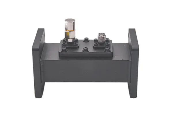
How to integrate waveguide components into existing RF systems
To integrate waveguide components into existing RF systems, first align frequencies: verify the system’s operating band (e.g., X-band 8–12GHz) overlaps with the component’s specified bandwidth (e.g., WR-90 covers 8.2–12.4GHz, ≥90% overlap). Use precision-machined flanges (e.g., standard WR-90, ±0.05mm tolerance) and torque to 15N·m with a calibrated wrench to minimize VSWR. Validate via vector network analyzer, […]
How to integrate waveguide components into existing RF systems Read More »