+86 29 8881 0979

August 30, 2025

How to design a waveguide antenna for high-frequency signals

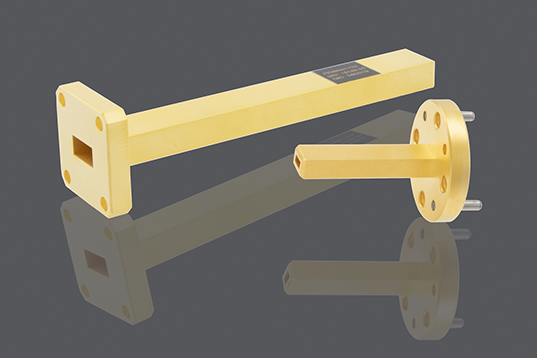
Designing a high-frequency waveguide antenna requires precise calculation of its internal dimensions to support the desired propagation mode, typically using a width of at least 0.7λ for the dominant mode. Careful selection of low-loss materials like copper and rigorous simulation for impedance matching are critical to minimize signal attenuation and maximize power transfer efficiency. Understanding […]

How to design a waveguide antenna for high-frequency signals Read More »

What are the 5 main challenges in waveguide antenna manufacturing

The 5 main challenges in waveguide antenna manufacturing are maintaining precise internal surface roughness (often under 1µm), achieving tight dimensional tolerances (±0.05mm), managing complex assembly and alignment, selecting suitable high-cost materials like copper, and ensuring efficient heat dissipation for high-power applications. ​​Precise Dimension Control​​ Even a tiny error, say ​​a deviation of just 0.05 mm​​,

What are the 5 main challenges in waveguide antenna manufacturing Read More »

How does a waveguide antenna work in microwave systems

A waveguide antenna works by guiding high-frequency microwaves (e.g., 1-100 GHz) from a source to the radiating aperture with minimal loss. It functions as a precision transition, converting confined waveguide modes into free-space radiation, often achieving gains over 20 dBi for directional applications like radar or satellite communications. ​​What is a Waveguide?​​ They are crucial

How does a waveguide antenna work in microwave systems Read More »

How to test waveguide components for signal loss

To test waveguide components for signal loss, use a vector network analyzer (VNA) to measure insertion loss by comparing the transmitted signal power through the component to a known reference, typically aiming for losses below 0.1 dB in high-performance systems. Ensure proper flange alignment and calibration with thru-reflect-line (TRL) kits for millimeter-wave accuracy. ​​Understanding Signal

How to test waveguide components for signal loss Read More »

What are the 3 best materials for waveguide components

​For waveguide components, brass is a top choice for its excellent machinability and good conductivity, often used in experimental kits. Aluminum is favored for its light weight and natural corrosion resistance, making it ideal for outdoor antennas. Copper offers the highest electrical conductivity, crucial for low-loss systems, though it is more expensive. Each material is

What are the 3 best materials for waveguide components Read More »

What are the 4 main types of waveguide feeds for antennas

The four main types of waveguide feeds are open-ended, small loop, folded dipole, and iris-coupled feeds. An open-ended waveguide provides broad beam radiation, often used for horns. A small loop offers magnetic coupling for polarization diversity. A folded dipole is a common probe for balanced excitation. Lastly, an iris-coupled feed uses a resonant slot for

What are the 4 main types of waveguide feeds for antennas Read More »

What are the 5 key differences between waveguides and coaxial cables

Waveguides and coaxial cables differ primarily in their operation and structure. Waveguides are hollow metal pipes transmitting signals as electromagnetic waves, ideal for high-power and high-frequency applications like radar (e.g., 10 GHz and above) with very low loss. In contrast, coaxial cables use a central conductor insulated and shielded by outer layers, suitable for lower

What are the 5 key differences between waveguides and coaxial cables Read More »

How to choose the right waveguide component for 5G antennas

Select waveguide components by evaluating frequency bands (e.g., 24-40 GHz for mmWave), insertion loss (<0.1 dB preferred), and power handling (e.g., 50W average). Ensure precise impedance matching and material compatibility (e.g., aluminum or brass) for optimal 5G antenna performance. Understanding 5G Frequency Bands Selecting the right waveguide component starts with a solid grasp of 5G

How to choose the right waveguide component for 5G antennas Read More »

How to optimize waveguide transfer switches for minimal signal loss

Optimize waveguide transfer switches by using precision-machined components with surface roughness below 0.1 µm, ensuring perfect alignment to minimize insertion loss to under 0.1 dB and VSWR below 1.05 through rigorous vector network analyzer testing. Understanding Waveguide Switch Basics A typical high-performance switch operating in the 18–40 GHz range might exhibit an insertion loss of

How to optimize waveguide transfer switches for minimal signal loss Read More »

Scroll to Top
Blank Form (#3)