+86 29 8881 0979

August 13, 2025

5 kinds of satellite communication antennas

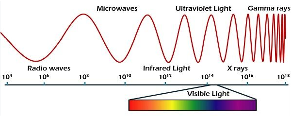
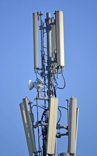
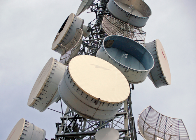
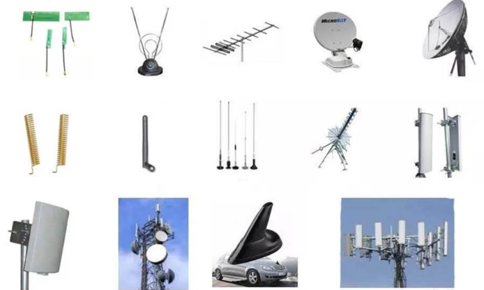
Satellite communication antennas include parabolic dishes (1-10m diameter for 2-30GHz signals), phased arrays (electronically steerable with 100+ elements), helical antennas (3-30dB gain for L/S-band), patch antennas (compact 2-6GHz for LEO satellites), and horn antennas (15-25dBi gain for ground station feeds). Each type offers distinct frequency coverage (UHF to Ka-band), polarization (linear/circular), and tracking capabilities for […]

5 kinds of satellite communication antennas Read More »

4 difference between near-field and far field EMI

Near-field EMI occurs within λ/2π distance (~4.8cm at 1GHz), showing reactive coupling (magnetic/electric dominance), while far-field EMI propagates beyond this range with electromagnetic waves. Near-field strength drops by 1/r² (electric) or 1/r³ (magnetic), versus far-field’s 1/r. Measurement requires H-field probes (<30MHz) or E-field probes, whereas far-field uses antennas (30MHz-6GHz). Near-field identifies component-level leaks; far-field assesses

4 difference between near-field and far field EMI Read More »

Top 6 Coupler Loops Manufacturers Market Leaders and Innovators

The top 6 coupler loop manufacturers include Murata (30% global RF market share), TDK (Q-factor >1000 at 1GHz), MACOM (military-grade to 40GHz), Anaren (low-loss <0.2dB), Johanson Technology (0402 to 1206 sizes), and Coilcraft (automotive-grade -55°C to +125°C). These innovators dominate 5G/WiFi-6 infrastructure with patented thin-film and multilayer ceramic technologies achieving ±0.5dB coupling accuracy. Top 3

Top 6 Coupler Loops Manufacturers Market Leaders and Innovators Read More »

What is the frequency range of the near-field probe

Near-field probes typically operate from 30MHz to 6GHz, with specialized models reaching 40GHz for millimeter-wave applications. Magnetic (H-field) probes use loop diameters (1-5cm) to optimize sensitivity below 1GHz, while electric (E-field) probes employ 1-10mm tips for high-frequency precision. Most maintain ±2dB accuracy when calibrated with a 10V/m reference field at 1GHz. What Near-Field Probes Do

What is the frequency range of the near-field probe Read More »

4 difference between near-field and far-field antenna measurements

Near-field measurements analyze antenna patterns within ​​1-2 wavelengths​​ (λ) using probes, capturing detailed phase/amplitude data for simulations, while far-field tests (beyond ​​2λ²/λ​​) assess radiation efficiency in open ranges or anechoic chambers. Near-field requires precise positioning (±1mm accuracy), whereas far-field needs ​​10+ meters​​ of clearance. Convert near-field data via Fourier transforms for far-field predictions. ​​Distance and

4 difference between near-field and far-field antenna measurements Read More »

3 differences between microwave transmission and radio wave signals

Microwave signals (1-100 GHz) offer high bandwidth (up to 10 Gbps) but require line-of-sight transmission, while radio waves (3 kHz-300 MHz) penetrate obstacles with lower data rates (1-100 Mbps). Microwaves use parabolic antennas for focused beams (1°-5° width), whereas radio employs omnidirectional antennas. Atmospheric absorption (e.g., 60 GHz oxygen absorption) affects microwaves more than radio

3 differences between microwave transmission and radio wave signals Read More »

6 side effects of introducing corners and bends into waveguides

Introducing bends in waveguides can cause ​​mode conversion (10-20% power loss)​​, increased ​​VSWR (up to 1.5:1)​​, and ​​attenuation spikes (0.1-3 dB per bend)​​. Sharp corners may trigger ​​higher-order modes​​, ​​field distortion (5-15% phase shift)​​, and ​​arcing risks​​ above 1 kW. Use ​​smooth 90° E/H bends​​ with radius ≥2× wavelength to minimize losses. For ​​Ka-band (26-40

6 side effects of introducing corners and bends into waveguides Read More »

3 differences between GSM antenna and microwave antenna

GSM antennas operate at lower frequencies (900/1800 MHz) for mobile communication, while microwave antennas use higher bands (2-60 GHz) for long-distance data links. GSM antennas have omnidirectional coverage (360°), whereas microwave antennas focus signals directionally (5°-30° beamwidth). Microwave antennas require precise alignment (±1° accuracy) for optimal performance, unlike GSM antennas’ plug-and-play installation. Size and Shape

3 differences between GSM antenna and microwave antenna Read More »

Top 5 reasons parabolic dish antennas are most commonly used in microwave applications

Parabolic dish antennas dominate microwave applications (1-100 GHz) due to their high gain (30-50 dBi achievable with 1-10m diameters), narrow beamwidth (1-5° for precise targeting), excellent directivity (>60dB front-to-back ratio), wide bandwidth (up to 40% fractional bandwidth), and efficient power handling (kW-level capacity). Their simple feed design (horn or dipole at focal point, typically 0.4-0.5×

Top 5 reasons parabolic dish antennas are most commonly used in microwave applications Read More »

The 7 benefits or advantages of an RF waveguide

RF waveguide has seven major advantages: 1. Low loss (only 0.1dB/m at 10GHz); 2. High power capacity (supports 10kW continuous wave); 3. Anti-interference (metal enclosed structure); 4. Wide bandwidth (WR-90 covers 8.2-12.4GHz); 5. High temperature resistance (>500℃); 6. High isolation (>80dB); 7. Suitable for millimeter wave transmission, commonly used in radar feeders and satellite communication

The 7 benefits or advantages of an RF waveguide Read More »

Scroll to Top
Blank Form (#3)