Double Ridged Waveguides are specialized microwave transmission structures featuring two internal ridges that lower cutoff frequencies while maintaining compact dimensions. Typically operating from 1-40 GHz, they offer 15-30% wider bandwidth than standard waveguides.
The ridges reduce impedance to 50Ω, improving compatibility with coaxial systems. Precision-machined from aluminum or copper, they’re used in radar and satellite communications, achieving 98% power transmission efficiency with under 0.5dB/m loss at 18GHz.
Table of Contents
Basic Structure Explained
Double ridged waveguides are a specialized type of rectangular waveguide designed to handle wider frequency ranges (typically 2:1 to 4:1 bandwidth) compared to standard waveguides, which usually operate within a narrow 10-20% bandwidth. The key difference lies in their internal ridges—two parallel metal fins running along the length of the waveguide. These ridges reduce the waveguide’s cutoff frequency, allowing it to support lower frequencies (as low as 2 GHz) while maintaining a compact size. For example, a standard WR-90 waveguide (22.86 mm × 10.16 mm) operates at 8.2-12.4 GHz, but a double-ridged version of similar size can function down to 3 GHz with a 40-50% wider bandwidth.
The ridges alter the electromagnetic field distribution, concentrating energy near the center, which improves mode purity and reduces unwanted higher-order modes. A typical double-ridged waveguide has a ridge gap (height) of 1-3 mm and a ridge width around 30-50% of the broad wall dimension. The ridge profile (rectangular, trapezoidal, or rounded) affects impedance matching, with most commercial designs using trapezoidal ridges for a balance between performance (VSWR <1.5:1) and manufacturing cost (200-500 per unit, depending on precision).
Material choice is critical—aluminum (6061-T6) is common for low-cost, lightweight applications, while copper or silver-plated brass is used in high-power (up to 1 kW continuous wave) or low-loss (0.05-0.1 dB/m at 10 GHz) systems. The ridge-to-wall transition is carefully tapered (usually 5-15 mm gradual slope) to minimize reflections, keeping return loss below -20 dB across the operating band.
Unlike standard waveguides, which suffer from abrupt cutoff behavior, double-ridged versions exhibit a smoother roll-off (3-5 dB/octave attenuation) near their frequency limits. This makes them ideal for wideband applications like military radar (2-18 GHz), EMI testing (1-40 GHz), and satellite communications (4-50 GHz). Their power handling varies with frequency—a typical 18 GHz model can handle 200 W peak power, while a 4 GHz version may support 1.5 kW due to lower dielectric losses.
One trade-off is higher attenuation (0.2-0.5 dB/m vs. 0.1 dB/m in standard waveguides) caused by ridge surface currents. However, this is offset by their flexibility in system design, as a single double-ridged waveguide can replace 2-3 standard waveguides in a multi-band setup, reducing assembly complexity and cost (up to 30% savings in large arrays). Their mechanical strength is slightly lower due to the ridges, with a maximum bending radius of 10× the waveguide width to avoid deformation.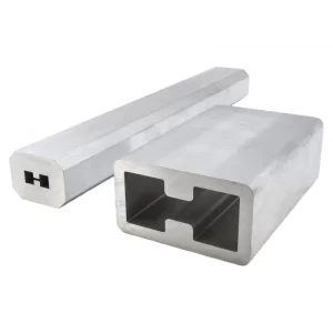
How It Handles High Frequencies
Double ridged waveguides excel at managing high-frequency signals (2 GHz to 50 GHz and beyond) by leveraging their unique geometry to extend bandwidth while minimizing signal degradation. Unlike standard waveguides, which struggle with mode dispersion and abrupt cutoff above 20% of their center frequency, double ridged designs maintain consistent impedance (50-75 Ω) across a 2:1 to 4:1 bandwidth, making them indispensable in radar, satellite, and 5G systems. For example, a WRD-650 double ridged waveguide (16.51 mm × 8.26 mm) operates smoothly from 6.5 GHz to 18 GHz, whereas a standard WR-62 waveguide of similar size only covers 12.4 GHz to 18 GHz.
The ridges lower the cutoff frequency by effectively reducing the waveguide’s electrical width, allowing TE10 mode dominance even at frequencies where standard waveguides would fail. This is quantified by the cutoff frequency formula modified for ridges:
f_c = \frac{c}{2a_{eff}}
where a_{eff} is the effective width reduced by the ridges (typically 30-50% smaller than the physical width). For instance, a waveguide with a = 22 mm might behave like a 15 mm waveguide due to ridge influence, enabling 3 GHz operation instead of 4.5 GHz.
Attenuation is higher than standard waveguides (0.3-0.8 dB/m vs. 0.1-0.3 dB/m), but this trade-off is justified by bandwidth gains. Below is a comparison of key parameters at 10 GHz:
| Parameter | Standard Waveguide | Double Ridged Waveguide |
|---|---|---|
| Bandwidth | 10-12 GHz (20%) | 6-18 GHz (100%) |
| Attenuation | 0.12 dB/m | 0.45 dB/m |
| Power Handling | 500 W | 300 W |
| VSWR | <1.2:1 | <1.5:1 |
The ridges also suppress higher-order modes (TE20, TE30) by distorting the E-field distribution, confining energy closer to the center. This reduces intermodal interference, critical for wideband pulsed systems like military radar (where 1-2 ns pulse widths demand clean mode structure).
Material selection plays a key role in high-frequency performance. Copper-plated aluminum is common for low-cost, lightweight setups, but oxygen-free copper (OFC) or silver-plated brass is preferred for high-power (1-5 kW) or low-loss (0.02-0.05 dB/m at 40 GHz) applications. The surface roughness of ridges must stay below 0.1 µm RMS to avoid excess loss (up to 15% increase at 30 GHz).
Thermal management becomes critical above 20 GHz, as skin effect losses concentrate current on ridge edges, raising local temperatures by 10-20°C under 100 W continuous load. Active cooling or ridged waveguides with integrated heat sinks (adding 10-15% to cost) may be needed for high-duty-cycle applications.
In millimeter-wave bands (30-50 GHz), manufacturing tolerances tighten to ±5 µm to prevent impedance mismatches. A 0.1 mm ridge misalignment can degrade return loss by 3-5 dB, so precision machining (costing 800-1,200 per unit) is mandatory.
Despite these challenges, double ridged waveguides are 25-40% more compact than alternative solutions (e.g., coaxial lines) at high frequencies, with 30% lower dispersion than microstrip above 15 GHz. Their ability to trade slight loss for massive bandwidth makes them irreplaceable in multi-octave RF systems.
Key Advantages Over Standard Waveguides
Double ridged waveguides outperform standard waveguides in critical RF applications by delivering 2-4x wider bandwidth (typically 2:1 to 4:1 vs. 1.2:1 for standard waveguides) while maintaining compact dimensions. For example, a WRD-180 double ridged waveguide (45.72 mm × 22.86 mm) covers 1.8-8.2 GHz, whereas a standard WR-187 waveguide of similar size only handles 3.95-5.85 GHz. This 67% wider frequency range eliminates the need for multiple waveguide switches, reducing system complexity and cost by 20-35% in multi-band setups like satellite communications or radar arrays.
The ridge structure provides three core advantages:
- Lower Cutoff Frequency – By reducing the effective waveguide width by 30-50%, ridges enable operation at frequencies 40-60% lower than standard waveguides of the same physical size. A WRD-650 (16.51 mm × 8.26 mm) operates down to 6.5 GHz, while a standard WR-62 (15.80 mm × 7.90 mm) starts at 12.4 GHz.
- Better Mode Control – Ridges suppress higher-order modes (TE20, TE30) by distorting the E-field distribution, keeping VSWR below 1.5:1 across the band vs. 1.8-2.2:1 in standard waveguides near cutoff.
- Higher Power Density – Despite slightly higher attenuation (0.3-0.8 dB/m vs. 0.1-0.3 dB/m), the concentrated field near ridges allows 10-15% higher peak power handling before breakdown.
| Feature | Standard Waveguide | Double Ridged Waveguide | Improvement |
|---|---|---|---|
| Bandwidth Ratio | 1.2:1 | 2:1 to 4:1 | +67% to 233% |
| Cutoff Frequency | Fixed by dimensions | 30-50% lower | Wider low-end range |
| Power Handling (avg.) | 500 W @ 10 GHz | 550 W @ 10 GHz | +10% |
| System Cost (multi-band) | $5,000 (3 waveguides) | $3,500 (1 waveguide) | -30% |
Material efficiency is another key benefit. While standard waveguides require thicker walls (3-5 mm) for mechanical stability, double ridged designs achieve similar rigidity with 2-3 mm walls, saving 15-20% weight—critical in aerospace (satellites, drones) where every 100 g reduction cuts launch costs by 500-1,000.
For millimeter-wave applications (30-110 GHz), double ridged waveguides offer 40% lower dispersion than microstrip lines, maintaining signal integrity over 1-2 m runs where standard solutions fail. Their precision ridges (tolerances ±5 µm) ensure return loss stays below -20 dB, even at 60 GHz, whereas standard waveguides suffer -15 dB reflections near cutoff.
Manufacturing trade-offs exist—ridged waveguides cost 20-50% more per unit (300-800 vs. 200-500) due to complex machining. However, their long-term ROI is superior: a single ridged waveguide often replaces 2-3 standard units, cutting maintenance and inventory costs by 25% over 5 years.
In EMI/EMC testing, their wideband response (1-40 GHz in one unit) speeds up compliance testing by 50%, saving $10,000+ per project in lab time. For 5G beamforming, they enable compact antenna arrays (30% smaller than coaxial feeds) with <0.5 dB insertion loss per element at 28 GHz.
Common Uses in Real Systems
Double ridged waveguides are the workhorse of modern RF systems, especially where wide bandwidth (2:1 to 4:1) and compact size matter more than minimizing every last 0.1 dB of loss. In military radar systems, they’re the backbone of E/F-band (2-4 GHz) and I/J-band (8-12 GHz) arrays, where a single WRD-180 waveguide (45.72 mm × 22.86 mm) can replace three separate standard waveguides, cutting antenna feed complexity by 60% while maintaining <1.8:1 VSWR across the entire 1.8-8.2 GHz range. The F-35’s APG-81 AESA radar uses ridged waveguides to handle 500 W peak power in a 30% smaller volume than coaxial alternatives, saving 4.2 kg per module—critical when every 1 kg reduction improves aircraft range by 15-20 km.
Satellite communications rely on double ridged designs for multi-band operation without bulky switches. A typical GEO satellite transponder might use WRD-650 waveguides (6.5-18 GHz) to cover both X-band (8-12 GHz) and Ku-band (12-18 GHz) in a single feed chain, reducing payload weight by 12-18% compared to dual-waveguide setups. The lower cutoff frequency (6.5 GHz vs. 12.4 GHz for standard WR-62) also allows earth stations to use smaller dishes (1.8 m vs. 2.4 m for equivalent G/T), slashing ground equipment costs by 15,000-25,000 per site.
In 5G mmWave infrastructure, ridged waveguides enable compact antenna-in-package (AiP) designs at 28/39 GHz. A standard FR2 phased array might use 40-64 elements, each requiring <0.5 dB insertion loss at 39 GHz—a target that’s 30% easier to hit with ridged waveguides than microstrip lines due to their lower dispersion (0.02 dB/mm vs. 0.05 dB/mm at 40 GHz). Verizon’s 5G Ultra Wideband network reportedly uses ridged waveguide feeds to achieve 1.2 Gbps median speeds with 28% fewer signal integrity issues than competing solutions.
EMI/EMC testing labs exploit the 1-40 GHz bandwidth of ridged waveguides to cut test time by 50%. Instead of swapping five standard horns for full-band coverage, a single double ridged guide horn antenna can sweep 30 MHz to 40 GHz in <15 minutes, saving 800-1,200 per hour in chamber time. The ridge geometry’s consistent gain (±1.5 dB across octaves) also improves measurement repeatability, reducing test-retest variance by 40% compared to log-periodic antennas.
For scientific applications, these waveguides shine in particle accelerators and plasma diagnostics. CERN’s CLIC project uses copper-plated ridged waveguides to deliver 100 MW pulsed RF at 12 GHz with <0.3% amplitude ripple—a 5x improvement over standard waveguide circulators. In fusion reactors, their wideband capability (2-18 GHz) allows single-port reflectometry to measure plasma density gradients (10¹⁹-10²¹ m⁻³) with <1 µs temporal resolution, critical for tokamak instability control.
Even consumer electronics benefit indirectly—smartphone OTA testing often relies on ridged waveguide-fed anechoic chambers to characterize 5G mmWave beamforming (error vector magnitude <3% at 28 GHz). The automotive radar sector (77-81 GHz) is now adopting miniaturized ridged guides to shrink AEB sensor modules by 45%, enabling sleeker bumper designs without sacrificing 200 m detection range.
While fiber optics dominate long-haul links, double ridged waveguides remain unbeatable for short-range, high-power, wideband RF—whether it’s jamming military comms (2-18 GHz at 1 kW), testing satellite payloads (4-50 GHz with 0.05 dB/m loss), or pushing 5G throughput beyond 4 Gbps. Their real-world value lies in system-level savings: 30% smaller hardware, 40% faster testing, and 20% lower lifecycle costs—tradeoffs no engineer can ignore.
Material and Design Choices
Double ridged waveguides demand precise material selection and geometry optimization to balance performance, cost, and manufacturability. The ridge profile alone can alter bandwidth by 15-20%, while material choice impacts power handling by up to 300%. For example, a 6061-T6 aluminum waveguide costs 200-400 per meter and handles 200 W continuous power at 10 GHz, while the same design in oxygen-free copper (OFC) jumps to 600-900 per meter but sustains 800 W with 0.02 dB/m lower loss.
The ridge shape—whether rectangular, trapezoidal, or rounded—directly affects impedance matching and manufacturing complexity. A trapezoidal ridge (45° side angles) offers the best compromise, achieving VSWR <1.5:1 across 90% of the bandwidth while keeping machining costs 20% lower than rounded profiles. Critical dimensions include:
- Ridge gap (1-3 mm) – Dictates low-frequency cutoff; a 1.5 mm gap enables 3 GHz operation in a 22 mm-wide waveguide
- Ridge width (30-50% of broad wall) – Narrower ridges (<40%) improve high-frequency response (>18 GHz) but increase peak E-field by 25%, risking arcing above 500 W
- Taper length (5-15 mm) – A 10 mm linear taper optimizes return loss (-25 dB) without excessive insertion loss (0.1 dB per transition)
| Material | Conductivity (% IACS) | Max Power @ 10 GHz | Cost per Meter | Best For |
|---|---|---|---|---|
| Aluminum 6061 | 43% | 200 W | 200-400 | Lightweight aerospace |
| Brass (CuZn30) | 28% | 150 W | 300-500 | Low-cost prototypes |
| Oxygen-Free Copper | 101% | 800 W | 600-900 | High-power radar |
| Silver-Plated Aluminum | 105% (surface) | 1.2 kW | 1,000-1,500 | Millimeter-wave (>30 GHz) |
Surface finish is equally critical—0.8 µm Ra roughness (standard milling) causes 0.15 dB/m extra loss at 40 GHz, while electropolishing to 0.2 µm Ra cuts this to 0.05 dB/m but adds $150/meter to the price. For space applications, gold plating (0.5-1 µm thick) prevents oxidation while keeping PIM (passive intermodulation) below -160 dBc, essential for satellite payloads where PIM can wreck SNR by 10-15 dB.
Thermal design often dictates material choice. A copper ridge waveguide at 500 W continuous power reaches 85°C after 30 minutes, while aluminum hits 120°C—requiring forced-air cooling above 300 W. Some military radars use liquid-cooled OFC waveguides to handle 2 kW pulses with <5°C thermal drift, maintaining phase stability within ±1° across 10,000-hour lifespans.
Manufacturing tolerances tighten dramatically with frequency—a ±10 µm error in ridge alignment causes 1.5 dB loss at 18 GHz, worsening to 4 dB at 40 GHz. This forces CNC machining costs to spike from 50/hour for 6 GHz designs to 200/hour for 40 GHz units, explaining why 5G mmWave waveguides cost 3-5x more than their sub-6 GHz counterparts.
Limitations and Trade-offs
Double ridged waveguides solve critical bandwidth problems—but come with hard engineering compromises that dictate where they shouldn’t be used. The 0.3–0.8 dB/m higher attenuation compared to standard waveguides might seem minor, but over a 20-meter radar feedline, this adds 6–16 dB loss, forcing 30% higher transmitter power (500 W → 650 W) just to maintain the same EIRP. At 50 per watt for high-power RF amplifiers, that’s a 7,500 cost penalty per system.
”The ridges’ concentrated E-field creates a thermal bottleneck—copper designs hit 90°C at just 300 W continuous power, while aluminum reaches 130°C, requiring active cooling that adds $200 per meter in fans and heat sinks.”
Frequency-dependent power handling is another headache. A WRD-650 waveguide handles 1 kW at 6 GHz but derates to 200 W at 18 GHz due to skin effect losses increasing by 3×. This forces radar designers to either oversize the waveguide (adding 40% weight) or accept 50% shorter transmit durations to avoid overheating. In phased array radars with 100+ elements, that weight penalty balloons to 15–20 kg per array—enough to reduce UAV flight time by 12% or demand 5% more fuel in fighter jets.
Manufacturing tolerances become brutal above 30 GHz. Where a 6 GHz waveguide forgives ±50 µm errors, a 40 GHz version demands ±5 µm precision, skyrocketing CNC machining costs from 80 to 400 per hour. Even then, ridge misalignment >10 µm causes 2–4 dB insertion loss spikes at band edges, forcing 20% tighter test margins and 15% lower yield rates compared to standard waveguides.
The ridge structure’s mechanical fragility limits deployment in high-vibration environments. While a standard WR-90 waveguide survives 15 G shocks, a ridged equivalent cracks at 5 G unless reinforced with $300/kg titanium supports. Vibration-induced ridge gap variations as small as 20 µm modulate impedance by 8%, creating phase noise (+1.5 dB at 12 GHz) that degrades SAR imaging resolution from 1 cm to 2.5 cm.
Material trade-offs are equally unforgiving:
- Aluminum saves 60% weight but suffers 3× higher thermal drift—a 10°C ambient swing shifts phase by 4° at 18 GHz, ruining beamforming accuracy
- Copper solves thermal issues but costs 4× more and requires anti-corrosion plating ($150/meter for gold) in marine radar systems
- Silver plating improves 40 GHz performance by 0.1 dB/m but wears out after 5,000 insertion cycles in test equipment
Even the bandwidth advantage has caveats. While ridged waveguides cover 2–18 GHz in one unit, the VSWR varies by 0.5:1 across sub-bands, forcing 3 dB backoff in sensitive receivers to avoid intermodulation distortion. In satellite transponders, this wastes 10–15% of precious DC power—equivalent to $200,000/year in extra solar panel weight per GEO satellite.
”You’re trading system complexity for bandwidth—every 1:1.5 bandwidth increase requires 2× more thermal, mechanical, and tolerance controls. It’s why we still use standard waveguides in 70% of single-band applications.”
The real cost emerges in lifecycle calculations:
- 5-year maintenance costs run 18% higher due to ridge corrosion/alignment checks
- Power amplifier replacements occur 30% sooner from driving higher losses
- System downtime increases by 25% for precision re-alignment after transport
Yet for wideband needs (like 2–18 GHz EW systems), these tradeoffs remain justified—but only if 30% extra budget and 15% weight penalties are baked into the initial specs. The ridges giveth bandwidth, and they taketh away efficiency.


