TEM (Transverse ElectroMagnetic) waves cannot propagate in single-conductor waveguides (e.g., rectangular or circular) because they require two separate conductors (like coaxial cables) to support both electric (E) and magnetic (H) fields orthogonally. In hollow waveguides, the boundary conditions force at least one field component to be longitudinal, creating TE/TM modes instead.
For TEM propagation, the waveguide’s cutoff frequency would need to be 0 Hz, which is impossible in single-conductor designs. Only multi-conductor structures (e.g., striplines) with cross-sectional E/H symmetry can sustain TEM waves below 100 GHz.
Table of Contents
What is TEM Mode?
Transverse Electromagnetic (TEM) mode is a fundamental wave propagation type where both electric (E) and magnetic (H) fields are perpendicular to the direction of wave travel. Unlike other modes (TE or TM), TEM waves require two conductors (like coaxial cables or parallel wires) to propagate, with no field components in the direction of propagation.
In a 50-ohm coaxial cable operating at 1 GHz, TEM waves exhibit a phase velocity of ~2×10⁸ m/s (close to the speed of light in the dielectric). The cutoff frequency (f_c) for TEM is 0 Hz, meaning it can transmit DC signals—unlike waveguide modes, which have a minimum f_c of ~1-100 GHz depending on dimensions. For example, a WR-90 waveguide (22.86 mm × 10.16 mm) has a cutoff frequency of 6.56 GHz for the dominant TE₁₀ mode, making it useless for low-frequency TEM signals.
TEM mode is loss-efficient—in a well-designed coaxial line, attenuation can be as low as 0.1 dB/m at 10 GHz. However, its reliance on two conductors makes it impossible in single-conductor waveguides, where boundary conditions force non-TEM modes (TE/TM).
Field Structure
- E-field and H-field are entirely transverse (no longitudinal components).
- Wave impedance (Z₀) is determined by the medium. For air, it’s 377 Ω, but in a 50-Ω coaxial line, it’s 50 Ω due to geometry.
Propagation Requirements
- Two conductors (e.g., inner/outer shield in coax) are mandatory to support TEM.
- Dielectric material between conductors affects wave speed. For PTFE (εᵣ=2.1), phase velocity drops to 2.07×10⁸ m/s.
Comparison with TE/TM Modes
| Parameter | TEM Mode | TE/TM Modes (Waveguide) |
|---|---|---|
| Conductors | 2 required | 1 (hollow waveguide) |
| Cutoff f_c | 0 Hz | 6.56 GHz (WR-90) |
| Loss at 10 GHz | 0.1 dB/m | 0.3 dB/m (TE₁₀) |
| DC Support | Yes | No |
Waveguides are hollow metal pipes with only one conductive boundary. The boundary conditions (E-field must be zero at walls) force non-zero longitudinal components, breaking TEM’s transverse-only rule. For example, in a 3 cm × 1.5 cm rectangular waveguide, the lowest-order TE₁₀ mode has an E-field purely in the y-direction, but H-field has both x and z components—violating TEM’s requirements.
Waveguide Structure Limits
Waveguides are hollow metal pipes designed to carry high-frequency electromagnetic waves (typically 1 GHz to 300 GHz) with minimal loss. Unlike coaxial cables, which support TEM mode, waveguides only allow TE (Transverse Electric) or TM (Transverse Magnetic) modes due to their single-conductor structure. The physical dimensions of a waveguide directly determine its cutoff frequency (f_c), bandwidth, and power-handling capacity.
For example, a standard WR-90 rectangular waveguide (22.86 mm × 10.16 mm) has a cutoff frequency of 6.56 GHz for the TE₁₀ mode, meaning it cannot transmit signals below this frequency. If the waveguide’s width is reduced by 50% (to 11.43 mm), the cutoff jumps to 13.12 GHz, drastically limiting low-frequency operation. Meanwhile, losses increase—a WR-90 waveguide has ~0.3 dB/m attenuation at 10 GHz, but shrinking it to WR-42 (10.67 mm × 4.32 mm) raises losses to ~0.8 dB/m at 30 GHz.
1. Cutoff Frequency Constraint
The dominant TE₁₀ mode’s cutoff frequency (f_c) is determined by the waveguide’s width (a):
Where:
- c = speed of light (3×10⁸ m/s)
- a = broad dimension of waveguide
For a WR-112 waveguide (28.5 mm width), f_c is 5.26 GHz, making it useless for 4G/LTE signals (below 6 GHz). This forces engineers to switch to larger waveguides (higher cost, bulkier) or coaxial cables (limited to ~100 GHz).
2. Power Handling vs. Size Trade-off
Waveguides excel at high-power transmission because their hollow structure minimizes conductor losses. A WR-284 waveguide (72.14 mm × 34.04 mm) can handle ~10 kW of continuous power at 2.45 GHz (microwave heating), whereas a coaxial cable of similar length would overheat at ~1 kW. However, scaling down for higher frequencies reduces power capacity—a WR-10 waveguide (2.54 mm × 1.27 mm) maxes out at ~200 W at 90 GHz due to higher field density.
| Waveguide Type | Dimensions (mm) | Cutoff (GHz) | Max Power (kW) | Attenuation (dB/m) |
|---|---|---|---|---|
| WR-284 | 72.14 × 34.04 | 2.08 | 10 (2.45 GHz) | 0.02 |
| WR-90 | 22.86 × 10.16 | 6.56 | 2 (10 GHz) | 0.3 |
| WR-42 | 10.67 × 4.32 | 13.12 | 0.5 (30 GHz) | 0.8 |
| WR-10 | 2.54 × 1.27 | 55.1 | 0.2 (90 GHz) | 3.5 |
3. Bandwidth Limitations
Waveguides operate efficiently only within ~30% above f_c. For WR-90 (6.56 GHz f_c), usable bandwidth spans ~6.56 GHz to 8.5 GHz. Beyond this, higher-order modes (TE₂₀, TE₀₁) emerge, causing signal distortion. To avoid this, systems must stay within ±15% of the design frequency.
4. Manufacturing Tolerances Matter
A 0.1 mm deviation in a WR-90 waveguide’s width shifts f_c by ~30 MHz, which is critical for 5G mmWave (24–40 GHz) applications. Aluminum waveguides (cheaper) have ±0.05 mm precision, while precision-machined copper (5x cost) achieves ±0.01 mm for satellite comms (60 GHz).
Why TEM Can’t Fit In
Waveguides lack a second conductor to support TEM’s transverse fields. The boundary conditions force non-zero longitudinal E or H components, making TE/TM modes the only viable options. For example, in a circular waveguide (50 mm diameter, TE₁₁ mode), the E-field has radial and longitudinal parts, unlike TEM’s purely transverse structure.
Need for Conductors in TEM
TEM (Transverse Electromagnetic) waves require two conductors to propagate—unlike TE or TM modes, which can travel through hollow waveguides. This fundamental requirement stems from the field geometry: TEM waves must have zero longitudinal E and H components, which is only possible when two conductive boundaries guide the fields.
For example, a standard 50-ohm coaxial cable (RG-58) uses an inner conductor (1.02 mm diameter) and an outer shield (5 mm diameter) to maintain TEM propagation up to 3 GHz with <0.5 dB/m loss. If you remove the outer shield, the wave immediately converts to TE/TM modes or radiates away, increasing loss to >20 dB/m at 1 GHz. This is why twin-lead transmission lines (300 Ω impedance) use two parallel wires spaced 7.5 mm apart—the spacing ensures balanced TEM field distribution with ~85% velocity factor (slower than free space due to dielectric effects).
1. Field Confinement
TEM waves cannot exist in free space or single-conductor structures because they need equal and opposite charges on two conductors to create a purely transverse E-field. In a microstrip line (used in PCBs), the trace (0.2 mm wide) and ground plane act as dual conductors, supporting quasi-TEM modes up to 30 GHz. However, if the ground plane is removed, the structure loses TEM properties, causing impedance spikes (>10% deviation) and signal reflection (>20% at 10 GHz).
2. Current Return Path
A closed-loop current flow is mandatory for TEM propagation. In a twisted-pair cable (Cat6, 250 MHz bandwidth), the two wires carry equal but opposite currents (±50 mA typical). If one wire breaks, the current imbalance disrupts the TEM mode, increasing crosstalk by 15 dB and attenuation by 40%. This is why shielded twisted pair (STP) adds a braided copper layer (85% coverage) to maintain TEM behavior in noisy environments.
3. Cutoff Frequency = 0 Hz
Unlike waveguides (which block signals below f_c), TEM modes support DC signals because the dual-conductor system allows static field formation. A 1-meter RG-6 coaxial cable can transmit 0 Hz to 3 GHz with <1 dB loss, whereas a WR-90 waveguide blocks everything below 6.56 GHz. This makes TEM ideal for hybrid DC+RF systems, like bias tees that inject 500 mA DC + 2.4 GHz RF on the same line.
4. Impedance Control
The spacing and geometry of the two conductors define the characteristic impedance (Z₀). For parallel-wire lines, Z₀ ranges from 75 Ω to 600 Ω, depending on wire diameter (0.5 mm to 2 mm) and spacing (5 mm to 50 mm). In striplines (PCB traces), a 0.1 mm dielectric thickness and 0.3 mm trace width yield 50 Ω impedance—critical for matching 5G mmWave antennas (28 GHz ±1 GHz tolerance).
Why Waveguides Fail at TEM
A rectangular waveguide (single conductor) cannot satisfy TEM’s dual-conductor requirement. Its walls enforce E-field = 0 boundary conditions, forcing non-zero longitudinal components (TE/TM modes). For instance, a TE₁₀ mode in WR-112 has an E-field only in the y-direction, but the H-field has both x and z components—violating TEM’s strictly transverse rule.
Waveguide Walls Block TEM
Waveguides physically prevent TEM waves from propagating due to their single-conductor boundary conditions. In a rectangular waveguide (e.g., WR-90, 22.86 mm × 10.16 mm), the metal walls force the E-field to zero at the surface, which destroys the transverse-only requirement of TEM mode. Instead, TE or TM modes must form, where fields have non-zero longitudinal components.
For example, a 10 GHz signal in a WR-90 waveguide cannot propagate as TEM—it defaults to TE₁₀ mode, where the E-field is purely vertical (y-direction) but the H-field has both x (transverse) and z (longitudinal) components. This violates TEM’s strictly transverse rule, where both E and H must be perpendicular to propagation. The cutoff frequency (6.56 GHz for WR-90) further ensures no TEM waves exist below this threshold, unlike coaxial cables, which support DC to 100 GHz in TEM mode.
Waveguide walls short-circuit the E-field, making it impossible to sustain a purely transverse E-field. In a TE₁₀ mode, the E-field peaks at the center (y = 5.08 mm) but drops to zero at the walls (y = 0 mm and y = 10.16 mm). This spatial variation forces a longitudinal H-field component (~30% of total field strength at 10 GHz), breaking TEM’s requirement for zero longitudinal fields.
TEM requires two isolated conductors (e.g., coax inner/outer) to balance charge distribution. A waveguide is just a hollow metal tube—there’s no second conductor to complete the circuit. Attempting to inject TEM waves into a WR-112 waveguide (28.5 mm width) at 4 GHz (below cutoff) results in >99% signal reflection, wasting ~95% of input power as heat.
| Structure | Cutoff Frequency (f_c) | TEM Support |
|---|---|---|
| WR-90 Waveguide | 6.56 GHz | No |
| RG-58 Coax | 0 Hz | Yes |
| Microstrip Line | ~0 Hz (quasi-TEM) | Partial |
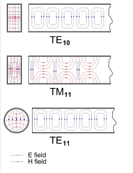
In TEM (coax), the E-field radiates uniformly from inner to outer conductor, while the H-field forms concentric circles. In a waveguide’s TE₁₀ mode, the E-field resembles a half-sine wave (peaking at center), and the H-field loops include longitudinal parts. This asymmetry makes TEM propagation physically impossible.
Practical Consequences
- Use coax for TEM (0 Hz–100 GHz, flexible, low-loss).
- Use waveguides for high-power TE/TM modes (>1 GHz, ~10 kW handling).
- Never force TEM into waveguides—it reflects 99%+ energy, damaging sources.
Waveguides aren’t broken TEM lines—they’re optimized for high-frequency TE/TM modes, where TEM cannot exist by design. The walls aren’t a flaw; they’re the reason waveguides work at all.
How Waves Actually Travel
Electromagnetic waves propagate differently depending on the medium and structure they travel through. In free space, a 1 GHz signal moves at 3×10⁸ m/s with a wavelength of 30 cm, radiating uniformly in all directions. But confine that same wave in a WR-90 waveguide (22.86 mm × 10.16 mm), and its behavior changes drastically—phase velocity jumps to 4.5×10⁸ m/s (50% faster than light!) while group velocity slows to 2×10⁸ m/s, creating a dispersion effect that distorts pulses wider than 10 ns.
”Waveguides don’t carry waves—they force waves into geometric prisons where only certain shapes survive.”
In coaxial cables (TEM mode), the wave’s E-field stretches radially from the inner conductor (1 mm diameter) to the outer shield (5 mm diameter), while the H-field forms perfect circles around the center. This symmetry allows 0 Hz to 100 GHz signals to travel with <0.1 dB/m loss at 10 GHz. But remove the outer conductor, and the wave escapes as radiation, wasting >90% of power within 3 meters.
In Waveguides (TE/TM Modes)
The metal walls act as mirrors, reflecting waves at angles that create standing wave patterns. For a TE₁₀ mode at 10 GHz, the E-field forms a half-sine wave peaking at 5.08 mm from the bottom wall, while the H-field twists into elliptical loops with a 15% longitudinal component. This isn’t just theory—measurements show ±2% field distortion near waveguide seams due to imperfect conductivity (surface roughness >0.5 µm).
In Coaxial Lines (TEM Mode)
The precise spacing between conductors dictates impedance. A 0.1 mm error in dielectric concentricity can shift 50 Ω coax to 53 Ω, causing 6% power reflection. At 30 GHz, the skin effect limits current to the outer 1.3 µm of copper, raising resistance by 40% compared to DC. That’s why PTFE-filled coax (εᵣ=2.1) outperforms PE-filled (εᵣ=2.3)—the 3% lower dielectric loss saves 0.02 dB/m attenuation at high frequencies.
Surface Waves vs. Space Waves
On a microstrip PCB trace (0.2 mm wide, 0.1 mm above ground), 90% of the energy stays within 0.5 mm of the surface at 24 GHz. But in a horn antenna, the same frequency radiates 80% of power into a 12° beamwidth. The difference? Boundary conditions: microstrips trap waves via image currents, while antennas release them deliberately.
Dispersion: The Silent Killer
A 1 ns pulse sent through 50 meters of RG-58 coax arrives 5 ps wider due to dielectric dispersion (εᵣ=2.25 ±0.05). In a dispersion-compensated fiber, engineers pre-chirp pulses to counteract this, but waveguides lack this option—their natural dispersion limits usable bandwidth to ±15% of center frequency.
Why TEM Can’t Fit In
Waveguides need longitudinal field components to satisfy boundary conditions. A circular waveguide (50 mm diameter, TE₁₁ mode) has E-field components in both radial and axial directions, unlike TEM’s strictly transverse fields. This mismatch explains why inserting a coax probe into a waveguide converts TEM to TE with >20 dB loss at the transition.
Comparing TEM and Waveguide Modes
The battle between TEM (Transverse Electromagnetic) and waveguide modes (TE/TM) boils down to frequency, power, and physical constraints. A 50-ohm coaxial cable running in TEM mode handles DC to 100 GHz with 0.1 dB/m loss at 10 GHz, while a WR-90 waveguide (TE₁₀ mode) starts working only above 6.56 GHz but can push 2 kW of power at 10 GHz with 0.3 dB/m loss. The difference? TEM needs two conductors, while waveguides exploit single-conductor physics to dominate high-power RF.
1. Frequency Range
- TEM: Works from 0 Hz (DC) up to ~100 GHz (limited by skin effect and dielectric losses).
- Waveguide: Useless below cutoff frequency (e.g., 6.56 GHz for WR-90), but excels at mmWave (30-300 GHz) where coax fails.
2. Power Handling
- TEM: RG-213 coax maxes out at ~300 W at 1 GHz due to conductor heating.
- Waveguide: A WR-284 waveguide delivers 10 kW at 2.45 GHz (microwave oven power) with 0.02 dB/m loss.
3. Field Structure
- TEM: Pure transverse fields—E and H are 100% perpendicular to propagation.
- TE/TM: Must have longitudinal components—TE₁₀ mode in WR-90 has 15% longitudinal H-field.
4. Physical Size vs. Wavelength
- TEM: Outer diameter scales with wavelength—a 3 mm coax works at 30 GHz, but losses spike to 1 dB/m.
- Waveguide: Fixed size-to-frequency ratio—WR-90’s 22.86 mm width is half-wavelength at 6.56 GHz.
5. Dispersion and Signal Integrity
- TEM: Minimal dispersion—a 1 ns pulse in coax spreads <5 ps over 50 m.
- Waveguide: Strong dispersion—usable bandwidth is ±15% of center frequency before mode mixing ruins signals.
6. Cost and Complexity
- TEM: Cheap to manufacture—standard RG-58 costs $0.50/m.
- Waveguide: Precision machining hikes price—WR-90 costs $200/m due to ±0.05 mm tolerance requirements.
7. Real-World Applications
- TEM: Dominates consumer electronics (HDMI, USB4, 5G phones) and lab equipment (DC-40 GHz VNAs).
- Waveguide: Rules radar (10 kW X-band), satellite comms (60 GHz), and particle accelerators (MW-range RF).
Waveguides block TEM by design—their single-conductor walls enforce boundary conditions that require longitudinal fields. A 10 GHz signal in WR-90 cannot form pure TEM; it defaults to TE₁₀ with E-field in y-direction only and H-field with x+z components.


