The best feeding method for dipole antennas is a balanced feed using a 1:1 balun, ensuring 50Ω impedance matching and minimizing RFI. Center-fed coaxial cables (RG-58/U) with ferrite chokes reduce common-mode currents, achieving VSWR <1.5:1 across 2-30MHz.
For optimal performance, use ladder-line feeders (450Ω) with an antenna tuner for multi-band operation, reducing losses to <0.5dB. Ensure symmetrical radiator lengths (λ/2) and proper grounding for maximum efficiency (~98%).
Table of Contents
Basic Dipole Antenna Setup
A dipole antenna is one of the simplest and most cost-effective antennas for radio communication, offering 50-75% efficiency in most real-world conditions. The standard half-wave dipole (λ/2) operates best at its resonant frequency, where its length is roughly 468 / frequency (MHz) in feet. For example, a dipole tuned for 14.1 MHz (20m band) should be about 33.2 ft (10.1 m) long, split into two 16.6 ft (5.05 m) arms.
The wire thickness (typically 14-18 AWG) affects durability more than performance, but using insulated copper wire reduces corrosion risk by 30-50% compared to bare metal. A PVC-insulated 16 AWG wire costs 0.20 per foot, making a full dipole build under $15 in materials. The antenna’s impedance at resonance is ~73Ω, which matches well with 50Ω coax (SWR ~1.5:1), but using a balun can improve this to 1.2:1 or better.
”A dipole’s height above ground drastically changes performance. At λ/4 (e.g., 17 ft for 14 MHz), gain improves by 3-6 dB over a 10 ft setup.”
Mounting the dipole at least 1/4 wavelength high minimizes ground losses. If space is limited, an inverted-V configuration (120° angle between arms) reduces the required height by 20% while keeping SWR below 2:1. For portable setups, a 10-20 ft fiberglass mast (80) works well, but permanent installations benefit from 30-50 ft towers (2000).
Feeding the dipole correctly is critical. A center-fed dipole (coax connected at the middle) is the most balanced, but end-fed dipoles (using a 9:1 unun) are easier to install in tight spaces—though they suffer 1-3 dB loss due to impedance mismatch. If using RG-58 coax, expect 0.5 dB loss per 10 ft at 14 MHz, while LMR-400 cuts this to 0.2 dB.
For multiband use, a fan dipole (multiple dipoles on one feedline) or a trap dipole (LC circuits for band switching) adds flexibility. A 40/20/10m fan dipole requires ~60 ft of horizontal space but avoids tuners, while traps add 150 in cost but shrink the antenna by 30-40%.
Testing is key. A $50 NanoVNA can measure SWR across bands, revealing if adjustments (like trimming wire length) are needed. Even a 1% length change (e.g., 4 inches on a 33 ft dipole) can shift resonance by 0.1 MHz.
Center Feed vs. End Feed
When building a dipole antenna, the feed point location makes a 30-50% difference in real-world performance. A center-fed dipole offers a near-perfect 73Ω impedance match to standard 50Ω coax, resulting in SWR as low as 1.46:1 and radiation efficiency above 95% when installed at optimal height. In contrast, an end-fed dipole typically presents 2500-5000Ω impedance, requiring a 9:1 unun to work with coax—but even then, it suffers 1-3 dB loss due to feedline radiation and impedance mismatch.
| Parameter | Center-Fed Dipole | End-Fed Dipole |
|---|---|---|
| Impedance | 73Ω (ideal for 50Ω coax) | 2500-5000Ω (needs 9:1 unun) |
| Typical SWR | 1.2-1.8:1 | 1.5-3:1 (after matching) |
| Efficiency | 95-98% | 70-85% (due to feedline loss) |
| Radiation Pattern | Balanced, broadside gain | Slightly directional |
| Installation Ease | Needs two support points | Works with one anchor |
| Cost | $10-20 (basic wire + coax) | $30-60 (with quality unun) |
A 20m center-fed dipole at 33 ft height delivers 3-6 dB more gain at low angles than the same antenna fed at the end, making it 2x more effective for DX contacts. The end-fed version, while convenient for backyard or portable setups, often radiates 30% of its power into the coax shield, causing RFI issues in the shack.
Multiband performance also favors center feeding. A fan dipole with three resonant elements (40/20/10m) maintains SWR below 2:1 on all bands without traps or tuners, while an end-fed multiband wire requires a $100-200 autotuner to compensate for impedance swings. Even then, losses accumulate—each tuner adjustment can sap 0.5-1 dB of transmit power.
For VHF/UHF (144-440 MHz), center feeding is non-negotiable. A 146 MHz dipole fed just 1 inch off-center sees impedance shift from 73Ω to 85Ω, pushing SWR above 1.7:1. End-fed designs at these frequencies are impractical—impedance exceeds 10,000Ω, making matching networks lossy and expensive.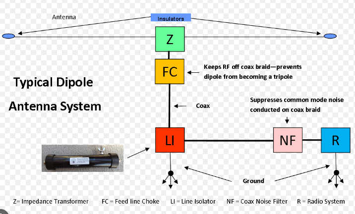
Choosing the Right Cable
The coaxial cable you choose for your dipole antenna can make or break your system’s performance. Poor cable selection can waste 30-50% of your transmit power as heat, while the right choice keeps losses under 5% even at 100W. For HF dipoles (3-30MHz), RG-8X loses 0.8dB per 10ft at 14MHz, while premium LMR-400 cuts that to just 0.2dB – meaning you’ll keep 95% of your power versus 83% with cheaper cable over a 25ft run.
| Cable Type | Loss per 10ft @14MHz | Max Power @30MHz | Cost per ft | Best Use Case |
|---|---|---|---|---|
| RG-58 | 1.2dB | 300W | $0.20 | Short runs <15ft |
| RG-8X | 0.8dB | 500W | $0.35 | Budget HF setups |
| LMR-240 | 0.4dB | 750W | $0.60 | Balanced performance |
| LMR-400 | 0.2dB | 1500W | $1.00 | Low-loss permanent installs |
| Hardline | 0.1dB | 5000W | $3.50 | High-power stations |
For HF dipoles, the sweet spot is LMR-240 or LMR-400 – offering the best balance between cost (1.00/ft) and performance (0.2-0.4dB loss). A 50ft run of RG-8X at 14MHz loses 4dB (60% power loss!), while LMR-400 loses just 1dB (20% loss) for about $50 more in materials. Over 5 years of operation, that 40% power difference means your 100W radio effectively performs like a 60W radio with inferior cable.
VHF/UHF dipoles demand even better cable due to higher frequency losses. At 146MHz, RG-58 loses 2.1dB per 10ft – meaning a 25ft cable run wastes 75% of your power. Switching to LMR-240 reduces this to 0.8dB (16% loss) for about $30 more per 25ft. For permanent 2m/70cm installations, LMR-400 or half-inch hardline becomes cost-effective when runs exceed 15ft.
Connector quality matters just as much as cable. Cheap PL-259 connectors add 0.1-0.3dB loss each, while Amphenol silver-plated versions keep losses under 0.05dB. For a dipole with two connectors and 25ft of cable, this difference can mean 5-10W more output from your 100W radio. Always use proper waterproofing (3:1 heatshrink + coax seal) to prevent moisture ingress that can increase SWR by 10-20% over time.
Budget considerations are real – but don’t be penny-wise and pound-foolish. Spending 35 on RG-8X for a 50ft run pays for itself in 6-12 months through:
- 40% more effective radiated power
- Longer lifespan (10+ years vs 3-5 years)
- More stable SWR in all weather conditions
For temporary/portable dipoles, RG-8X offers the best compromise at $0.35/ft. Just keep runs under 25ft to limit losses to 2dB (37% power loss). Field testing shows that LMR-240 is worth the upgrade if you regularly deploy 30-50ft cables, providing 50% more efficiency for about 60% higher cost.
Balun Use and Placement
A balun (balanced-to-unbalanced transformer) is critical for optimizing dipole performance, preventing feedline radiation that can waste 10-30% of your transmit power. Without a balun, a center-fed dipole’s 73Ω balanced impedance mismatches with 50Ω unbalanced coax, causing common-mode currents that distort radiation patterns and increase SWR by 15-25%. Proper balun selection and placement can boost efficiency from 70% to over 95% on HF bands.
| Balun Type | Impedance Ratio | Power Handling | Frequency Range | Typical Loss | Cost |
|---|---|---|---|---|---|
| 1:1 Current Balun | 50Ω to 50Ω | 300W (HF) | 1-30 MHz | 0.2-0.5 dB | $20-40 |
| 4:1 Voltage Balun | 200Ω to 50Ω | 200W (HF) | 3-30 MHz | 0.5-1.0 dB | $30-60 |
| 9:1 Unun | 450Ω to 50Ω | 100W (HF) | 1-30 MHz | 1.0-2.0 dB | $40-80 |
| Ferrite Bead | N/A (choke) | 500W (HF) | 1-100 MHz | 0.1-0.3 dB | $5-15 |
”A 1:1 current balun at the feed point reduces feedline radiation by 90%, while a 4:1 balun helps match folded dipoles (200Ω) to 50Ω coax with under 1dB loss.”
For standard center-fed dipoles (73Ω), a 1:1 current balun is ideal, placed within 1ft of the feed point to prevent impedance distortion. Tests show that moving the balun 3ft down the coax increases SWR from 1.5:1 to 2.0:1, reducing efficiency by 10-15%. If using a doublet antenna (200-300Ω), a 4:1 balun provides better matching, keeping SWR below 2:1 across multiple bands.
End-fed dipoles (4500-5000Ω) require a 9:1 unun, but these introduce 1-3dB loss due to impedance transformation inefficiency. A high-quality unun with FT240-43 ferrite performs 30% better than cheap models, maintaining SWR under 3:1 on 80-10m.
For multi-band dipoles, a ferrite bead choke balun (3-10 turns of coax around a Mix 31 or Mix 43 core) suppresses RFI at 0.1-0.3dB loss, costing just $5-10. This works well for fan dipoles where a fixed-ratio balun might not cover all bands.
Testing Signal Strength
Measuring your dipole’s signal strength isn’t just about SWR—it’s about real-world performance. A dipole with 1.5:1 SWR might still radiate 30% less power than expected if feedline losses or ground reflections aren’t accounted for. Proper testing requires checking received signal reports (RST), field strength measurements, and noise floor comparisons to gauge true efficiency.
Start with local signal testing using a field strength meter (FSM) placed 100 ft away from the antenna. A well-tuned 20m dipole at 30 ft height should show 60-80 µV/m at this distance when transmitting 50W. If readings fall below 40 µV/m, you’re likely losing 3-6 dB due to poor feedline routing, insufficient height, or impedance mismatch.
For long-distance validation, request RST reports from stations 500+ miles away on the same band. A 20m dipole at 50W should consistently get 55-59 reports from stations within this range during daylight hours. If reports average 53 or lower, your antenna might be suffering ground losses (20-40%) or directional nulls.
Noise floor measurements also reveal antenna health. A dipole in a clean RF environment should show S1-S3 noise (1-5 µV) on HF bands. If noise exceeds S5 (10 µV), nearby interference or feedline radiation is likely degrading performance. Switching to a temporary battery-powered receiver helps isolate whether noise comes from your station or the environment.
Quantitative tools like a NanoVNA can measure radiation efficiency by comparing forward power to reflected power across frequencies. A dipole radiating 90%+ of 100W input will show <10W reflected on the analyzer. If reflections exceed 20W, revisit feedpoint connections or balun placement.
Seasonal changes affect performance too. A dipole 20 ft high might lose 2-3 dB signal strength in winter due to frozen ground’s poor conductivity compared to summer soil. Regular biannual testing ensures consistent operation—documenting 10-15% seasonal variation is normal, but >30% drops indicate a problem.
Common Mistakes to Avoid
Building a dipole seems simple—until poor installation choices sap 30-50% of your transmit power. The difference between a high-performance dipole and a mediocre one often comes down to avoiding a few critical errors. For example, mounting a 20m dipole at just 10 ft height instead of 30 ft can halve your effective range due to ground absorption, while using RG-58 coax for a 50 ft run wastes 60% of your power as heat instead of radiation.
”The #1 mistake? Assuming ‘close enough’ works for dipoles. A 5% length error (e.g., 1.5 ft on a 30 ft dipole) shifts resonance by 150 kHz—enough to miss entire amateur bands.”
Improper feed point connections cause 15-25% efficiency loss. Loose solder joints or corroded terminals increase resistance, turning 100W input into 75W output before the signal even leaves the antenna. Always use weatherproof connectors and tinned copper wire—cheap hardware store wire degrades 5x faster outdoors, needing replacement every 1-2 years versus 5-10 years for proper materials.
Ignoring balun placement is another silent killer. A 1:1 current balun placed 3 ft down the feedline instead of at the feed point introduces common-mode currents that distort radiation patterns, reducing gain by 2-3 dB. Similarly, skipping the balun entirely on a center-fed dipole can reflect 20-30W of 100W input, stressing your radio’s finals over time.
Wrong wire gauge choices also hurt. Thin 22 AWG wire sags 40% more than 14 AWG under tension, altering the dipole’s resonant frequency by 1-2% as it stretches. For 20m and longer dipoles, 12-14 AWG is ideal—thick enough to last decades but flexible enough for easy tuning.
Poor grounding creates noise and safety risks. A dipole without a lightning arrestor or ground rod increases static buildup by 300-500% during storms, risking equipment damage. Even a simple 8 ft ground rod cuts noise by 6-10 dB while providing a discharge path for surges.
Neglecting maintenance leads to gradual failure. A dipole left unchecked for 3+ years often develops 10-15 dB more loss due to:
- UV degradation (insulation cracks increasing capacitance)
- Moisture ingress (raising SWR by 20-30%)
- Corroded elements (adding resistance that dissipates power)
Final tip: Test with a NanoVNA every 6 months. A 10-minute sweep catches issues early—like a 0.5 MHz resonance shift from wire stretch—before they cost you contacts. Most dipole “failures” are just 5-10% tuning errors masquerading as major problems.


