LPDA antennas excel in wideband signal interception (70MHz–18GHz), with 10–15dBi gain; used in electronic warfare to track 5+ comms protocols simultaneously, exploiting their frequency-agnostic radiation pattern for consistent, multi-spectrum surveillance.
Table of Contents
How an LPDA Works
A simple half-wave dipole antenna is designed to be highly efficient at one specific frequency. For example, a dipole cut for the 100 MHz FM radio band (about 1.5 meters long per side) will perform poorly outside a narrow range of about 95 MHz to 105 MHz. Its performance, measured by the Voltage Standing Wave Ratio (VSWR), quickly degrades outside this range, often exceeding a VSWR of 3:1, which means a significant portion of your transmitter’s power is being reflected back instead of radiated. The LPDA solves this fundamental limitation.
| Feature | Typical LPDA Specification Example (VHF/UHF) |
| Frequency Range | 100 MHz – 800 MHz |
| Number of Elements | 14 – 18 |
| Boom Length | 1.2 – 2.0 meters |
| Gain | 7.5 – 9.5 dBi |
| Typical VSWR | < 1.7:1 across entire range |
| Front-to-Back Ratio | > 20 dB |
The ratio between the lengths and spacings of adjacent elements is a constant, known as the scaling factor (τ, tau), which typically has a value between 0.88 and 0.95. A higher τ value, like 0.95, often results in smoother performance but requires a longer boom for the same frequency coverage compared to a lower τ of 0.88.At any given operating frequency within the antenna’s design range, a cluster of 3 or 4 adjacent elements becomes electrically active, forming the “active region.” The longest element in this cluster is approximately a half-wavelength long at the operating frequency and acts as a reflector, while the shorter elements ahead of it act as directors.
For instance, at 150 MHz, the active region might be around the 5th and 6th longest elements, but at 500 MHz, it shifts to the 3rd and 4th shortest elements. This is why the LPDA can maintain a consistent impedance very close to 50 ohms and a stable radiation pattern across a bandwidth that can be 5:1 or even 10:1, such as covering from 100 MHz to 1000 MHz with a single antenna. The gain variation across this huge range is typically kept within a tight window of ±1.5 dB, a key advantage over simpler broadband antennas like discones, which often suffer from lower gain. The physical size is directly proportional to the lowest frequency needed; covering 50 MHz requires elements over 2.5 meters long, while an LPDA for 2.4 GHz Wi-Fi can be smaller than 15 cm.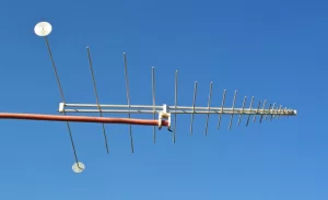
Wide Frequency Range
While a standard Yagi-Uda antenna might offer a bandwidth of 5% to 10% around its center frequency, a well-designed LPDA can achieve a bandwidth of 50% to 100% or even more. This means a single LPDA designed for the VHF band can seamlessly cover the entire 30 MHz to 300 MHz spectrum without requiring any tuning or matching networks. For instance, a single LPDA model can be specified to cover the entire 174-230 MHz and 470-862 MHz bands used for digital television across different regions, a total span of nearly 700 MHz. This eliminates the need for multiple antennas and complex combining systems, reducing installation points, cabling, and overall system cost by as much as 40-60% compared to a multi-antenna setup.
This wideband capability is a direct result of the antenna’s geometric scaling. The performance at any frequency is determined by a small group of elements that are approximately a half-wavelength long at that frequency. As the frequency changes, the “active region” simply moves along the boom to a different set of appropriately sized elements.
Consider a cellular network operator deploying equipment for 4G LTE and 5G NR in a single sector. The required frequencies might span from 698 MHz to 960 MHz for low-band and 1.7 GHz to 2.2 GHz for mid-band services. Using traditional narrowband antennas would necessitate at least two, and possibly three or four, separate antennas per sector, each with its own radio frequency line. The wind load, structural weight, and visual impact increase significantly. An LPDA, however, can be engineered to cover the entire 690 MHz to 2.7 GHz range with a single physical unit. This single antenna would exhibit a gain variation of less than ±2 dB across the entire spectrum and maintain a Voltage Standing Wave Ratio (VSWR) below 1.8:1, ensuring that over 95% of the transmitted power is effectively radiated rather than reflected back into the transmitter, which can damage sensitive electronics over time.
A scanner enthusiast using one LPDA antenna can monitor air traffic at 118–137 MHz, public safety communications at 150–174 MHz, and weather satellite downlinks at 137 MHz without any mechanical or electrical adjustments. achieving a 10:1 frequency ratio (e.g., 100 MHz to 1000 MHz) requires a boom length sufficient to accommodate the longest element for the lowest frequency, which would be approximately 1.5 meters long for 100 MHz. The scaling factor (τ) and the spacing ratio (σ) are carefully balanced during the 3 to 6 week design and simulation phase to optimize this gain-bandwidth performance, creating a device that performs predictably across a spectrum width that would be impossible for a single resonant antenna.
TV Reception
For receiving over-the-air digital television signals, the Log-Periodic Dipole Array (LPDA) is often the ideal antenna design. In regions like North America, TV channels occupy a vast frequency range from 54 MHz to 88 MHz (VHF Low Band, channels 2-6), 174 to 216 MHz (VHF High Band, channels 7-13), and 470 to 698 MHz (UHF Band, channels 14-51). A high-gain Yagi antenna might be optimized for a 10% bandwidth on a single band, but an LPDA can provide consistent performance across all three bands simultaneously.
- VHF Low Band (Ch. 2-6): 54 – 88 MHz. Requires long elements; a dipole for Channel 2 is about 2.7 meters wide.
- VHF High Band (Ch. 7-13): 174 – 216 MHz. A dipole for Channel 7 is about 0.85 meters wide.
- UHF Band (Ch. 14-51): 470 – 698 MHz. A dipole for Channel 51 is about 0.32 meters wide.
The primary advantage for TV reception is the antenna’s ability to maintain a stable 75-ohm impedance across this entire 644 MHz range. Digital TV signals, like ATSC 1.0 and 3.0, are digital transmissions, but they are broadcast as very low-power analog RF signals, typically from 100 kW to 1000 kW ERP. A poor antenna with a high VSWR (above 2.5:1) can cause signal packet loss exceeding 5%, leading to pixelation and complete signal dropouts, even with a strong reported signal strength.
An LPDA designed for TV reception typically maintains a VSWR below 1.8:1, ensuring over 95% of the received signal power is efficiently transferred to the coaxial cable with minimal loss. The forward gain of a typical outdoor TV LPDA ranges from 7.5 dBi to 12 dBi, which is 3 to 6 times more sensitive than a simple dipole or set-top antenna. This extra gain is critical for receiving signals from transmitters located 30 to 80 kilometers away, especially in areas with slight obstructions. The antenna’s front-to-back ratio, often greater than 20 dB, is crucial for rejecting multipath interference. This occurs when signals bounce off buildings or hills, arriving at the antenna a few microseconds later than the direct signal, which can corrupt the digital data stream. By rejecting signals from the rear by a factor of 100:1 in power, the LPDA significantly improves signal clarity.
Pros and Cons Listed
For a project requiring coverage from 80 MHz to 2 GHz, an LPDA might be the only viable single-antenna solution, offering a 10:1 bandwidth ratio. However, for a mission-critical communication link on a single frequency like 446.0 MHz, a different antenna would likely provide better performance per dollar.
- Key Advantage: Covers a 50% to 100%+ bandwidth with a consistent ~8 dBi gain and low <1.8:1 VSWR.
- Key Disadvantage: Has a larger size and weight for a given gain compared to a same-frequency Yagi, with a typical wind load area 40% greater.
The following table provides a direct comparison with other common antenna types for a specific use case.
| Feature | Log-Periodic Dipole Array (LPDA) | Yagi-Uda Antenna | Discone Antenna |
| Typical Bandwidth | 50% to 100%+ (e.g., 100-1000 MHz) | 5% to 10% (e.g., 144-146 MHz) | 10:1 Ratio or more (e.g., 100-1000 MHz) |
| Gain at Center Frequency | 7-12 dBi (relatively flat across band) | 12-19 dBi (high, but narrowband) | ~2 dBi (near-omnidirectional, low gain) |
| VSWR Performance | < 1.8:1 across entire design band | < 1.5:1 at center frequency, degrades rapidly | ~2.0:1 (acceptable but not excellent) |
| Size for 150 MHz Center | 2-meter boom, 15 elements, ~2.5 kg | 1.5-meter boom, 12 elements, ~1.5 kg | 1-meter height, ~1 kg |
| Relative Material Cost | $$ (complex feed structure, many elements) | $ (simple driven element, passive directors) | $$ (precision cone and disc construction) |
For a broadcaster, using a single high-power LPDA capable of handling 5 kW across the 470-862 MHz UHF band is significantly more economical and structurally simpler than installing and feeding two separate antennas, reducing tower rental costs by an estimated 30%. The mechanical reliability is also high; with no electrically active moving parts, a well-built LPDA made from 6061-T6 aluminum and 304 stainless steel hardware can have a service life exceeding 20 years, surviving wind speeds of up 130 km/h with minimal deviation.The most significant con is the lower gain-to-size ratio compared to a Yagi. A Yagi designed for 435 MHz with a 1.2-meter boom can achieve a gain of 14 dBi. An LPDA covering 400-500 MHz with the same 1.2-meter boom length will typically max out at 9.5 dBi of gain. This 4.5 dB difference is substantial; it means the LPDA’s signal strength is only about 35% as powerful as the Yagi’s at that specific frequency.
The physical size and weight are also greater for equivalent low-frequency performance. An LPDA for 50 MHz requires a boom length of over 4 meters and a turning radius of several meters, making it unsuitable for most residential lots, whereas a multi-element Yagi for the same frequency could be 25% shorter. The feed system complexity inherent in the design also leads to slightly higher signal loss between the longest and shortest elements; this can result in a 0.5 dB to 1 dB efficiency penalty compared to the direct feed of a single dipole.
Compared to a Yagi Antenna
The choice between a Log-Periodic Dipole Array (LPDA) and a Yagi-Uda antenna is a fundamental decision in RF system design, boiling down to a trade-off between bandwidth and peak performance. A Yagi is a specialist, engineered for exceptional performance within a narrow slice of spectrum, often as little as 2% of its center frequency (e.g., 144-148 MHz). An LPDA is a generalist, providing good, consistent performance over a much wider range, typically 50% to 100% of its center frequency (e.g., 400-1000 MHz). The selection criteria are primarily driven by the required frequency coverage, available physical space, and budget, with cost differences ranging from 20% to 100% for comparable size antennas.
- Bandwidth vs. Gain: A Yagi offers ~12 dBi gain on a single band; an LPDA offers ~8 dBi gain across multiple bands.
- Size vs. Performance: For the same lowest frequency, an LPDA requires a ~25% longer boom than a Yagi for equivalent gain at that frequency.
- Complexity vs. Cost: The LPDA’s interconnected feed system increases part count and manufacturing time, raising its unit cost by ~30% over a similar Yagi.
The following table provides a direct, quantified comparison of these two antenna types for a common application.
A Yagi’s performance is tightly coupled to the precise electrical length of its elements. If you operate 1% away from its designed center frequency (e.g., at 441 MHz instead of 435 MHz), its gain may drop by 0.5 dB and its VSWR may rise from 1.3:1 to 1.8:1, reflecting 5% more power back to the transmitter. If you move 10% away (to 390 MHz), the antenna may become practically unusable, with a VSWR exceeding 5:1 and a 60% power loss.
Conversely, an LPDA’s performance is almost identical at 390 MHz and 480 MHz because the active region simply shifts to a different set of elements. This makes the LPDA the only practical choice for applications like TV reception (requiring 54-698 MHz coverage) or wideband scanning (e.g., 25-1300 MHz), where a single Yagi is physically incapable of covering the span.However, for dedicated point-to-point links, the Yagi’s superior gain-to-size ratio is decisive. A 1.2-meter long 435 MHz Yagi can achieve 14 dBi of gain, concentrating the signal 25 times more powerfully in one direction than an isotropic radiator. An LPDA of the same length covering 400-500 MHz would only provide about 9.5 dBi, a 4.5 dB deficit meaning the Yagi’s signal is effectively 2.8 times stronger.
Choosing the Right LPDA
An LPDA’s performance is defined by its lowest and highest design frequencies. The lowest frequency dictates the size of the longest element, which is approximately a quarter-wavelength long. For example, to receive signals down to 50 MHz, the longest element will be about 1.4 meters per side, resulting in a total antenna width of nearly 2.8 meters and a boom length of 3 to 4 meters. If your application only requires coverage from 400 MHz to 1000 MHz, you can choose a much more compact model with a boom length of under 1 meter and a largest element of about 0.35 meters.
Specifying a range wider than necessary, like 50-3000 MHz for a 450 MHz cellular application, often means paying a 20-30% premium for a larger, more complex antenna and accepting a 1-2 dB lower gain across your specific band of interest compared to a model optimized for 400-1000 MHz.The next crucial specification is the forward gain, typically stated in dBi (decibels relative to an isotropic radiator). Gain is directly related to the antenna’s directivity and boom length. A compact indoor LPDA might have a gain of 5 dBi, effectively doubling the effective radiated power compared to a simple dipole. A full-size outdoor model for TV reception might offer 10.5 dBi, increasing signal strength by a factor of 11 times. However, higher gain comes with trade-offs.
Each 3 dBi increase in gain requires roughly a 40-50% increase in boom length and element count. An LPDA with 12 dBi gain might have an 18-element array on a 2.4-meter boom, while an 8 dBi model might only need an 8-element array on a 0.9-meter boom. This directly impacts wind load, which increases by the square of the dimensions; the 2.4-meter antenna will experience nearly 4 times the wind pressure of the 0.9-meter model, requiring a more robust and expensive mast capable of handling a 50 kg load versus a 15 kg load.


