Wideband horn antennas typically span 2–18 GHz, some reaching 40 GHz; flared geometry keeps VSWR <1.2 across range, ideal for radar/comms needing multi-octave spectral coverage with stable gain.
Table of Contents
The Standard Horn
A rectangular waveguide operating in the dominant TE10 mode. This waveguide has a fundamental cutoff frequency, f_c, below which signals cannot propagate. For a common WR-90 waveguide (internal dimensions: 22.86 mm x 10.16 mm), this f_cis approximately 6.56 GHz, setting the absolute lower limit. The upper bound, around 13.5 GHz for WR-90, is where the next higher-order mode (TE20) can excite, creating unpredictable radiation patterns. Therefore, the practical operating band for a standard horn fed by WR-90 is 8.2 GHz to 12.4 GHz (X-Band), a ~40% bandwidth. With a well-designed flare optimizing the phase center, you can achieve a consistent gain, typically between 15 dBi and 25 dBi, with side-lobe levels often better than -10 dB to -15 dB below the main beam. The voltage standing wave ratio (VSWR) across this band is typically a very efficient <1.5:1, ensuring minimal reflected power.
The Fundamental Bandwidth Limitation
Its fundamental cutoff frequency, f_c, is determined solely by its wider internal dimension a, using the formula f_c = c / 2a, where cis the speed of light. For a ubiquitous WR-90 waveguide (a= 22.86 mm), this f_cis 6.56 GHz. This is an absolute barrier: signals below this frequency experience catastrophic attenuation, dropping over 100 dB within a few centimeters of guide length. The horn simply cannot radiate what its feed cannot carry. The upper frequency is constrained by the emergence of higher-order modes, like TE20, which begin to propagate around f = c / a(13.12 GHz for WR-90). These modes create distorted, unpredictable radiation patterns. Therefore, the theoretical single-mode bandwidth of a rectangular waveguide is a 2:1 ratio, but practical impedance matching and pattern stability concerns shrink the usablebandwidth for a horn antenna to a reliable 40-60%.
1. It All Starts with the Waveguide’s Physical Dimensions
The designation “WR-90” literally encodes the wider dimension: ’90’ means 0.90 inches, which is 22.86 mm. The narrower dimension bis typically half of a(10.16 mm). These aren’t arbitrary choices; they are optimized for a single-mode operation and power handling. If you need a horn for a lower frequency band, you must scale the entire structure up. A WR-137 guide for C-band (a= 34.85 mm) has a f_cof 4.30 GHz. A smaller agives a higher f_c, and a larger agives a lower f_c. You cannot feed a WR-90 waveguide with a 5 GHz signal and expect efficient operation; the rejection will be better than 40 dB just a few centimeters into the guide.
2. The Single-Mode “Sweet Spot”
Operating within the 1.25f_c to 1.9f_c range is the sweet spot. For WR-90, this is roughly 8.2 GHz to 12.4 GHz. Within this ~40% band, the TE10 mode propagates cleanly. The horn’s flare is designed to provide a smooth impedance transition from the waveguide’s ~500-ohm impedance to free space’s 377 ohms over this specific range, yielding a good Voltage Standing Wave Ratio (VSWR) of < 1.5:1.
As you approach the band edges, performance degrades predictably:
- Near Lower Bandedge (~8.2 GHz): The guide wavelength is long, and the impedance match becomes trickier. VSWR might creep up to 1.7:1 or 1.8:1. The horn’s aperture is electrically small, resulting in lower gain and a wider beamwidth.
- Near Upper Bandedge (~12.4 GHz): The risk is the excitation of the TE20 mode. If the horn or feed has any slight asymmetry or discontinuity, this mode can propagate. In the radiation pattern, this manifests as a squinted main beam or a significant rise in sidelobe levels, sometimes increasing from a nominal -15 dB to a problematic -8 dB.
3. Why You Can’t Just Make the Horn Flare Super Wideband
A simple horn design is optimized for a single frequency. As you deviate from that design frequency, the difference in path length from the feed point to the center of the aperture versus the edge (the phase error) increases. At frequencies 20% above the design frequency, this error can cause the beam to defocus, lowering gain and raising sidelobes. At frequencies 20% below, the aperture is not fully illuminated, reducing efficiency. The horn’s physical dimensions are tuned to a specific frequency range, and its efficiency drops off outside that range.
4. A Comparison of Standard Waveguide Bands
The following table illustrates the fundamental limitation. The waveguide standard dictates the horn’s entire physical size and absolute operational boundaries. The key takeaway is the consistent reduction from the theoretical waveguide band to the practical horn operating band.
| Waveguide Standard | Internal Dimension ‘a’ (mm) | Theoretical Waveguide Band (GHz) | Practical Horn Operating Band (GHz) | Approx. Usable Bandwidth | Common Application Band |
|---|---|---|---|---|---|
| WR-229 | 58.17 | 2.60 – 4.00 | 3.30 – 4.90 | ~39% | C-Band (Satellite Downlink) |
| WR-137 | 34.85 | 4.30 – 6.60 | 5.30 – 7.70 | ~37% | C-Band (Weather Radar) |
| WR-90 | 22.86 | 6.56 – 10.00 | 8.20 – 12.40 | ~41% | X-Band (Radar, Satellite) |
| WR-62 | 15.80 | 9.49 – 14.50 | 12.00 – 17.50 | ~37% | Ku-Band (Satellite, Radar) |
| WR-42 | 10.67 | 14.05 – 21.50 | 17.50 – 25.50 | ~37% | K-Band (Radar, Automotive) |
Note on Bandwidth Calculation: The Approx. Usable Bandwidth is calculated as 2*(f_high - f_low) / (f_high + f_low) * 100%. The consistency in the ~37-41% range across different bands highlights the fundamental physical constraint. Pushing a design beyond this typically requires compromising on performance parameters like side-lobe level or VSWR, which must stay below 2.0:1 for most applications. 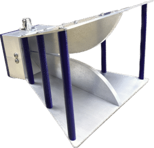
Gain and Pattern Performance Across the Band
The aperture, perhaps 90 mm wide, is electrically only about 2.5 wavelengths across. At the high end, 12.4 GHz, the wavelength shrinks to 24.2 mm, making the same aperture electrically 3.7 wavelengths wide. This electrical size difference dictates everything: gain can easily swing by 3 dB, the -3 dB beamwidth can narrow by 8-10 degrees, and sidelobe levels can improve by 4-5 dB. The antenna is essentially a different device at each frequency point within its band, a fact critical for any system link budget or measurement setup.
1. antenna louder, focuses better,go up in frequency
Gain is a measure of how effectively an antenna concentrates radiation in a specific direction. For a horn, the maximum achievable gain, known as the directivity, is primarily a function of aperture area in terms of wavelengths squared (A/λ²).
- The Math: The directivity (D) for a pyramidal horn with aperture dimensions (E-plane: a, H-plane: b) is approximately D ≈ (4π/λ²) * η * (ab)*, where η is the aperture efficiency (typically between 0.5 and 0.8 for a standard horn). The λ² term in the denominator is the key. As frequency increases, λ decreases, and (1/λ²) increases.
- A Real-World Example: Take a horn optimized for X-band with a 90 mm x 60 mm aperture.
- At 8.5 GHz (λ = 35.3 mm), the effective aperture area is roughly 0.52 * (90 * 60) = 2808 mm². The directivity calculates to about 18.8 dBi.
- At 12.0 GHz (λ = 25.0 mm), the physical aperture is unchanged, but the effective area in wavelengths squared increases. The directivity jumps to approximately 21.5 dBi.
- This 2.7 dB increase is significant—it radiated power is effectively 1.86 times more concentrated at the high end than at the low end.
2. How the beam shape squishes and stretches with frequency
The half-power beamwidth (HPBW) is inversely proportional to the electrical size of the aperture. The beamwidth will be widest at the lowest frequency and narrowest at the highest.
- Beamwidth Calculations: Approximate formulas for HPBW in the principal planes are:
- E-Plane HPBW (degrees) ≈ 56° / (a/λ)
- H-Plane HPBW (degrees) ≈ 67° / (b/λ)
- Tracking the Beam: Using the same 90 mm x 60 mm aperture horn:
- At 8.5 GHz: a/λ = 90/35.3 ≈ 2.55, b/λ = 60/35.3 ≈ 1.70.
- E-Plane HPBW ≈ 56°/2.55 ≈ 22.0°
- H-Plane HPBW ≈ 67°/1.70 ≈ 39.4°
- At 12.0 GHz: a/λ = 90/25.0 = 3.60, b/λ = 60/25.0 = 2.40.
- E-Plane HPBW ≈ 56°/3.60 ≈ 15.6°
- H-Plane HPBW ≈ 67°/2.40 ≈ 27.9°
- At 8.5 GHz: a/λ = 90/35.3 ≈ 2.55, b/λ = 60/35.3 ≈ 1.70.
- This represents a beam narrowing of over 6° in the E-plane and 11° in the H-plane. A system designed for a 25° beam at the center frequency might suffer from misalignment issues at the band edges.
3. The subtle dance of sidelobes and nulls across the spectrum
Sidelobe levels (SLL) are dictated by the amplitude and phase distribution of the electromagnetic field across the antenna’s aperture. In a standard horn, the illumination is primarily defined by the dominant TE10 mode from the waveguide, which has a cosine (tapered) distribution across the H-plane.
- Low-Frequency Pattern: At the low end of the band, the aperture is less illuminated, and the taper is more significant. This generally results in lower SLL, often around -12 dB to -15 dB for the first sidelobe in the H-plane, because the energy is more concentrated in the center, reducing spillover.
- High-Frequency Pattern: As frequency increases, the illumination of the aperture becomes more uniform. This improves directivity but also increases the first sidelobe level, which can rise to -10 dB or higher. The pattern also develops more distinct nulls between sidelobes.
- Phase Error Impact: If the horn is not optimized (e.g., too short for its flare angle), phase error across the aperture will smear the pattern. This can cause the first null to fill in, reducing null depth from a typical -20 dB to a shallow -12 dB, and raise the average sidelobe level by 3-5 dB, scattering energy in unwanted directions. Patterns should be simulated or measured at least at three points: lower bandedge, center, and upper bandedge to capture this evolution.
4. The real-world impact on VSWR and impedance matching
While the horn’s flare is designed for a smooth impedance transition, the match is never perfect across the entire band. The Voltage Standing Wave Ratio (VSWR) will exhibit a minimum, typically at the design center frequency.
- A well-designed horn might have a VSWR of 1.15:1 at 10.5 GHz.
- This value will gradually increase towards the band edges, reaching 1.4:1 or even 1.7:1 at 8.2 GHz and 12.4 GHz.
- This increase corresponds to a rise in reflected power from about 1% at the center to 4% at the edges. For high-power systems, even this small percentage can represent a significant amount of energy reflected back into the transmitter, requiring robust circulator or isolator specifications.
Dual-Ridged Horn Antenna
Forget the limitations of standard gain horns with their narrow 1.5:1 bandwidth. A dual-ridged horn antenna (DRHA) is the engineered solution for extreme frequency agility, typically covering a 10:1 to 40:1 range—like 700 MHz to 18 GHz—in a single, compact package. The core innovation lies in the tapered ridges integrated into the waveguide. These ridges systematically lower the cut-off frequency of the fundamental mode by over 60%, enabling efficient operation at wavelengths much larger than the waveguide’s physical dimensions would allow. This design achieves an average voltage standing wave ratio (VSWR) of < 2.5:1 across its entire band, but it introduces a significant gain slope: while you might get a healthy +15 dBi at 18 GHz, this can drop to just +2 to +5 dBi at the lowest frequency. This trade-off is critical for applications like EMC testing, where a single DRHA can replace an entire rack of narrowband antennas, reducing test setup time by 70% or more and providing a calibrated amplitude stability of ±0.5 dB for accurate compliance measurements.
Decoding the Specifications
A specified frequency range of 1 GHz to 18 GHz does not mean the antenna performs uniformly across that entire 18:1 bandwidth. The critical detail is the gain curve, which can plummet from +15 dBi at the high end to a mere +3 dBi at the low end, a 12 dB difference that translates to a factor of 16x in required transmit power or received signal strength. Similarly, a VSWR specification of < 2.5:1seems good, but it represents an 11% power reflection back into your system, causing 0.5 dB of insertion loss that compounds with connector wear. A 1 dB miscalibration in your antenna factor, often hidden within a ±1.5 dBuncertainty claim, leads to a 26% error in field strength measurement, enough to falsely pass or fail a multi-million dollar product in EMC compliance testing.
1. Frequency Range
Manufacturers define the operational band where VSWR is below a threshold, like 2.0:1. However, this electrical bandwidth often outpaces the radiative efficiency.
- Low-Frequency Cutoff and Aperture Size: The fundamental limit is physics, not design. For a DRHA to be an effective radiator at 700 MHz (wavelength λ ≈ 43 cm), its largest aperture dimension must be significantly greater than λ/2, or ~21.5 cm. An antenna with a 25 cm wide aperture will be drastically more efficient at 700 MHz than one with a 15 cm aperture, even if both are rated for the same low frequency. The smaller antenna might achieve the VSWR spec but with a gain of -5 dBi, making it practically useless.
- High-Frequency Roll-off: Above 18 GHz, performance is limited by manufacturing tolerances and the excitation of higher-order modes. Surface imperfections smaller than 0.1 mm can scatter energy at 40 GHz.
2. Gain
Presenting a single gain value for a wideband antenna is misleading. The gain is a direct function of effective aperture.
- Calculating the Slope: Aperture area is fixed. Gain is proportional to
4π * A_effective / λ². As frequency doubles, λ halves, and gain increases by 6 dB in an ideal, lossless case. A real-world DRHA might show a gain increase from 5 dBi at 1 GHz to 17 dBi at 18 GHz, following a roughly +8 dB per decade slope. The ±1 dB deviation from this slope indicates design quality. - The dBi vs. dBic Confusion: Datasheets always report gain in dBi (relative to an isotropic radiator). For polarization-sensitive applications, ensure the antenna maintains a stable polarization purity, typically >20 dB axial ratio, across the band. A drop to <10 dB axial ratio represents a 3 dB+ loss in signal strength for a circularly polarized link.
3. VSWR
Voltage Standing Wave Ratio is the most critical, and most misunderstood, spec. It’s a measure of impedance match.
- The Real Cost of a High VSWR: A VSWR of 2.0:1 means 90% of your power is radiated, and 10% is reflected. This reflected power heats up your power amplifier and raises the system noise floor. If your amplifier delivers 100W, 10W is bouncing back, potentially driving it into compression or failure. A VSWR of 3.0:1 wastes 25% of your power.
- It’s a Curve, Not a Ceiling: A spec claiming “VSWR < 2.5:1” typically describes the performance across 80% of the band. Examine the detailed VSWR plot. Peaks to 3.5:1 at the band edges are common and define the real operational limits. A 0.5 increase in VSWR due to a damaged connector directly reduces your system’s dynamic range.
4. Antenna Factor
For measurement antennas, the Antenna Factor (AF) is more important than gain. It converts the voltage at the antenna terminals to the incident field strength.
- Accuracy and Traceability: A high-quality DRHA ships with a calibrated AF table, often in 50 MHz increments, traceable to a national lab like NIST. The calibration uncertainty might be
±0.3 dBat mid-band but widen to±1.0 dBat the frequency extremes. This uncertainty budget must be added to your total measurement system error. - The 1 dB Rule: A 1 dB error in the AF value creates a 12% error in your calculated field strength. For a CISPR Class B radiated emissions limit of 40 dBμV/m at 1 GHz, a 1 dB AF error could mean the difference between a pass at 39.5 dBμV/m and a fail at 40.5 dBμV/m, with significant financial consequences.
5. Beamwidth
The Half-Power Beamwidth (HPBW) tells you how focused the antenna’s “flashlight” beam is. Like gain, it’s frequency-dependent.
- The Inverse Relationship: Beamwidth is inversely proportional to gain. At 1 GHz with a gain of 5 dBi, the E-plane and H-plane beamwidths might be very wide, around 120 degrees. At 18 GHz with 17 dBi gain, the beamwidth narrows to approximately 20 degrees.
- Implications for Measurement: When performing antenna pattern measurements or site attenuation validation, the 3 dB beamwidth dictates the required angular sampling resolution. To accurately map a pattern with a 20-degree beamwidth, you must take readings at least every 5 degrees. Using a 10-degree step on a 120-degree beamwidth pattern wastes time and provides excessive data, while the same step on a 20-degree beamwidth misses critical pattern details.
Real-World Applications
In electromagnetic compatibility (EMC) testing, a horn’s calibrated antenna factor (AF) accuracy of ±0.5 dBis the difference between a product passing a $10,000 compliance test and facing costly re-designs. For a direction-finding system, the phase center stability of the horn, which can shift by less than 2 cm over a 2-18 GHz range, determines geo-location accuracy to within 5 meters. In high-power applications, the average power handling of 100 watts at 1 GHz drops to just 10 watts at 18 GHz due to increased conductor losses, a critical detail for survivability.
1. EMC/EMI Testing
In the EMC lab, the DRHA is a calibrated measurement transducer, not just an antenna. Its primary job is to convert field strength into a quantifiable voltage at a spectrum analyzer.
- The Cost of a Single Antenna vs. a Rack of Horns: A single high-quality DRHA covering 80 MHz to 18 GHz costs between 15,000. Replacing it with a set of standard gain horns to cover the same range (e.g., 80-300 MHz, 300-1000 MHz, 1-6 GHz, 6-18 GHz) requires at least four antennas, costing over $20,000 and requiring a complex, error-prone switching system. The DRHA solution reduces set-up time by 70% and eliminates connector repeatability errors from hundreds of mating cycles per test.
- Antenna Factor Uncertainty Dictates Product Fate: Regulatory limits like FCC Part 15 or MIL-STD-461 are absolute. A product must radiate below a specific dBµV/m level. Your measurement system’s accuracy is defined by the expanded uncertainty (k=2) of the antenna factor. A horn with a
±1.0 dBuncertainty at 18 GHz means your measured 40 dBµV/m could be a true 39 dBµV/m (pass) or 41 dBµV/m (fail). Labs using horns with traceable calibrations bearing a±0.5 dBuncertainty have a lower margin of error, reducing false failure risks. This calibration is typically valid for 24 months, with a recalibration cost of 1,500. - Amplitude Stability for Site Validation: Before testing, standards like ANSI C63.25 require validating the test site’s attenuation (NSA). This involves measuring signal strength over a 3-meter path at multiple antenna heights.
2. Direction Finding (DF) and Signal Intelligence (SIGINT)
Here, the DRHA’s wide instantaneous bandwidth allows a single antenna array to monitor vast swaths of the spectrum for fleeting signals.
- Phase Center Stability Enables Accuracy: DF systems use time-difference-of-arrival (TDOA) or amplitude comparison between multiple antennas. If the phase center of the horn moves significantly with frequency, the calculated angle of arrival will be wrong. A high-quality DF horn specifies a phase center variation of less than 15 mm from 1-18 GHz. A 10 mm error in phase center location at 10 GHz (wavelength = 30 mm) introduces a 120-degree phase error, rendering the DF estimate useless. The physical mounting point of the antenna is not the same as its effective phase center, and this discrepancy must be precisely mapped.
- Handling High-Density Signals: In an urban environment, a SIGINT system might need to identify and locate signals from 500 MHz to 6 GHz simultaneously. A DRHA connected to a bank of high-speed analog-to-digital converters (ADCs) can capture a 2 GHz wide chunk of spectrum in a single snapshot. The antenna’s linear phase response ensures that pulses with rise times as fast as 100 picoseconds are not distorted, preserving the signal’s “fingerprint” for identification.
3. High-Power Pulse Applications and Radar
Dual-ridge horns are used in ultrawideband (UWB) radar systems for ground-penetrating radar (GPR) or through-wall imaging, where they must handle short, high-power pulses.
- Time-Domain Fidelity Over Flat Gain: For radar, the antenna’s impulse response is more critical than its flat gain. The goal is to transmit a clean, short pulse—e.g., a 1 nanosecond pulse—without “ringing.” The horn’s VSWR and its behavior in the time domain are critical. A poor design will have a “late-time” response, adding a trailing signal that masks close-in targets. The system’s range resolution, δR, is given by
δR = c * τ / 2, where τ is the pulse width. A 1 ns pulse provides a 15 cm resolution. Antenna-induced ringing that spreads the effective pulse to 2 ns degrades resolution to 30 cm, making it impossible to distinguish two separate objects closer than that distance. - Peak vs. Average Power: These systems use very low duty cycles—perhaps 0.1%. A horn rated for 1 kW peak power but only 10 W average power is perfectly suited for transmitting 1 kW pulses that are 1 µs long at a 1 kHz repetition rate. The average power is
1,000W * 0.000001s * 1000/s = 1W, well within the limit. The critical factor is the voltage standoff capability of the feed region; a high-power horn will have carefully rounded ridges to prevent air breakdown (arcing) at field strengths exceeding 3,000 V/cm.
4. Satellite Communication and Aerospace Testing
Aerospace platforms contain systems operating from UHF to Ku-band. A DRHA is used to test these platforms for self-compatibility and susceptibility.
- Testing Over Distance in Anechoic Chambers: In a chamber simulating free-space path loss, signal strength drops with the square of the distance (
1/R²). To test a satellite receiver’s sensitivity, a test signal might need to be generated from 10 meters away. The power required at the antenna input is calculated as:Power_required (dBm) = Sensitivity (dBm) + Path Loss (dB). At 12 GHz, path loss over 10 meters is approximately20*log10( (4π*10) / 0.025 ) ≈ 72 dB. If the receiver sensitivity is -90 dBm, you need-90 dBm + 72 dB = -18 dBmdelivered to the test antenna. A DRHA with 20 dBi gain at 12 GHz focuses that power effectively, while a lower-gain antenna would require an amplifier with 10 dB more output power, a significant cost increase. - Multi-Band Signal Simulation: A single DRHA can be used to simulate multiple threat signals—a 1.5 GHz GPS jammer, a 5 GHz WiFi interferer, and a 15 GHz radar signal—to an aircraft’s navigation system simultaneously.
Wideband Horns
Enter the wideband horn antenna. While a standard gain horn might offer a respectable 1.5:1 bandwidth ratio (e.g., covering 12-18 GHz), a modern double-ridged waveguide horn shatters that limitation. These workhorses routinely deliver 10:1 to 20:1 bandwidth ratios, allowing a single antenna, like a common 1-18 GHz model, to replace an entire rack of 6 to 8 narrower-band units. it’s a direct 80% reduction in calibration overhead and a 60% decrease in test setup complexity. Whether you’re sweeping a device from 80 MHz to 6 GHz for EMC compliance or measuring a radar cross-section with 2 GHz of instantaneous bandwidth, these antennas provide the critical >15 dB return loss and stable 5 dBi to 15 dBi gain needed for accurate, repeatable measurements.
Core Design & Operating Principles
A standard horn with a 130 mm x 98 mm physical aperture might be limited by its waveguide feed to 12-18 GHz. Adding double ridges to that same physical size can push the low-frequency performance down to 2.0 GHz or lower, achieving a continuous bandwidth of over 10:1. This extension isn’t free; achieving operation from 800 MHz to 18 GHz (a 22.5:1 ratio) forces a complex trade-off between impedance matching, phase linearity, and gain flatness.
How the ridged waveguide pushes the low end 70% lower
An empty metal waveguide has a cut-off frequency, acting like a high-pass filter. A standard rectangular waveguide (like WR-229) cuts off around 3.95 GHz. Signals can’t propagate efficiently below this. Introducing ridges fundamentally alters the waveguide’s equivalent circuit model.
- The Capacitance Effect: The ridges act as a concentrated capacitor between the top and bottom walls. The calculation is no longer based solely on the broadwall dimension ‘a’ but includes a factor ‘k’ related to the ridge gap ‘d’. As the d/a ratio decreases from 1.0 (no ridge) to 0.1, the cut-off frequency can drop to 20-30% of its original value. This is how a double-ridged waveguide, physically the same size as a WR-229, can drop the low-end cutoff from 3.95 GHz down to 800 MHz.
- Impedance Transformation: A standard waveguide’s characteristic impedance is typically 400-500 ohms, a poor match for a 50-ohm coaxial cable. The second critical function of the ridges is to lower this impedance. By carefully profiling the ridges, the impedance can be smoothly transitioned to 50 ohms, enabling broadband matching.
A precise taper from waveguide to free space
The ridged waveguide solves the feed problem, but the energy still needs to be efficiently launched into free space (377 ohms). The flare section performs this final impedance transformation while controlling the wavefront.
- Exponential vs. Linear Taper Trade-off: The flare profile isn’t arbitrary. An exponential taper curve (H(x) = H0 * e^(kx)) provides the best impedance matching and phase center stability over the widest bandwidth but is more complex to machine. A linear or compound taper (e.g., dual-curvature) is easier to manufacture but can introduce small ripples at the band edges, potentially worsening VSWR from 2.0:1 to 2.8:1 at 1 GHz and 18 GHz. High-performance antennas use custom curves optimized through precise electromagnetic simulations.
- Phase Center: The measurement’s reference point: An antenna has an apparent point of radiation origin, its phase center. In a wideband horn, this point moves as frequency changes. A good design keeps this movement on the order of wavelengths. A well-designed 1-18 GHz horn can maintain its phase center within a ±5 mm range over 80% of its band.
Dual-ridge vs. quad-ridge
Standard dual-ridge horns provide linear polarization (vertical or horizontal). But many modern applications demand more flexible polarization agility.
- Dual-Ridge Horns: Feature two ridges connected to the inner and outer conductors of the coaxial feed. Their -3 dB beamwidths in the principal planes (E- and H-plane) can differ by 10 to 20 degrees. Cross-polarization isolation is typically on the order of -15 dB, meaning about 3% of the power leaks into the unintended polarization.
- Quad-Ridge Horns: Incorporate two orthogonal pairs of ridges, fed by a sophisticated 90-degree hybrid coupler. This enables true dual-polarized operation. The key advantage is the ability to electronically switch between left-hand circular, right-hand circular, and any linear polarization without physically rotating the antenna. This flexibility comes at a high cost: bandwidth is often reduced to 5:1 (e.g., 2-10 GHz), VSWR performance is slightly worse (typically < 2.5:1), and manufacturing cost can be 3 to 5 times that of a comparable dual-ridge horn. The feed network also introduces about 0.5 dB of additional insertion loss, directly reducing the antenna’s effective gain.
gain, power, and size
Wide bandwidth isn’t free; it’s the result of careful engineering compromises.
- Gain and Efficiency: Compared to a standard horn of the same aperture size, a wideband horn’s gain is 3 to 6 dBi lower. This is partly because energy is distributed around and between the ridges rather than filling the entire waveguide cross-section, reducing the effective aperture area. Radiation efficiency can drop to 60% at the low band edge while exceeding 85% at the high end.
- Power Handling: The sharp edges of the ridges create high electric field density. At high peak power levels (like a 100 kW radar pulse), this increases the risk of voltage breakdown (arcing). Consequently, the average power handling of wideband horns is often limited to 50 to 200 watts, while a similar-sized standard horn might handle 1 kW easily. Power capacity is inversely proportional to the square root of frequency, so it might be 100 W at 1 GHz but drop to 20 W at 18 GHz.
- Size and Weight: To achieve 10 dBi gain at 1 GHz, the horn requires a massive physical size (aperture can exceed 400 mm). A typical 1-18 GHz double-ridge horn often weighs 3 to 5 kilograms, whereas a standard horn covering only 12-18 GHz might weigh 0.5 kilograms.
Critical Performance Parameters
A 0.5 dB change in gain flatness can be the difference between a passing and failing EMC test. A VSWR spec of 2.0:1 versus 3.0:1 translates to a 10% difference in power delivered to the antenna—critical for radar transmitters. Phase center stability, often overlooked, must be tighter than ±5 mm for accurate RCS measurements at 18 GHz; a shift of ±20 mm introduces a phase error exceeding 12 degrees, rendering data questionable. These parameters are interlocked: pushing for a 5:1 bandwidth ratio on a $1,500 budget forces compromises, typically raising VSWR above 2.5:1 and reducing peak power handling to under 100 W.
Frequency Range
The absolute range, often defined by a VSWR < 3.0:1, indicates the frequencies where the antenna will not be damaged. The usablerange, defined by stable radiation patterns and consistent gain, is often narrower.
- Low-End Roll-Off: Performance degrades rapidly below the cut-off. An antenna rated for 1-18 GHz might see its gain drop from 5 dBi at 1.2 GHz to -2 dBi at 1.0 GHz. The beamwidth also widens significantly, exceeding 100 degrees, making the antenna pattern unpredictable.
- High-End Limitations: Above the maximum frequency, higher-order modes can excite, creating pattern distortion. Sidelobes may increase from -20 dBc to -12 dBc, and the main beam can develop nulls or split. Manufacturers typically specify the range over which the main beam remains single-lobed.
Why average gain matters more than peak
Gain, measured in dBi, indicates directivity. However, the variation of gain across the band is often more critical than its peak value.
- The 6 dB per Octave Rule: A theoretically perfect constant-aperture antenna sees its gain increase by 6 dB each time the frequency doubles. A horn might have 5 dBi at 1 GHz and 17 dBi at 18 GHz—a 12 dB range. Most commercial horns use profile shaping to flatten this response. A high-quality horn might specify a gain flatness of ±3 dBi across the band, for example, 10 dBi ±3 dBi from 2-18 GHz.
- Calibration Uncertainty: A gain variation of ±3 dB means the antenna factor (AF) used in EMC testing has the same uncertainty. This ±3 dB error propagates directly into field strength measurements. For precise compliance testing, a ±1.5 dB gain flatness specification is often required, which can double the antenna’s cost.
The measure of wasted power
Voltage Standing Wave Ratio quantifies impedance matching. It’s a direct measure of efficiency.
- The Power Calculation: A VSWR of 2.0:1 means 90% of the power from the source is delivered to the antenna; 10% is reflected. A VSWR of 3.0:1 drops the delivered power to 75%, with 25% reflected. In a 100 W transmission system, that VSWR 3.0:1 specification wastes 25 W back into the amplifier, potentially causing damage.
- Cascading System Performance: In a receiver chain, a poor antenna VSWR interacts with the cable VSWR. An antenna with VSWR 3.0:1 connected via a cable with VSWR 1.5:1 can create standing waves that introduce several dB of amplitude uncertainty. For systems requiring high accuracy, a VSWR < 2.0:1 (Return Loss > 14 dB) is the minimum benchmark.
How coverage changes with frequency
The -3 dB beamwidth defines the antenna’s angular coverage. It is inversely proportional to gain and frequency.
- Predictable Variation: A horn might have a 70-degree H-plane beamwidth at 2 GHz that narrows to 15 degrees at 18 GHz.
- Beam Squint: In dual-linear or circularly polarized (quad-ridge) horns, the phase centers for different polarizations are not perfectly coincident. This can cause a phenomenon called beam squint, where the peak of the beam for vertical polarization is offset from the horizontal by up to 5 degrees at the band edges, introducing pointing error.
The hidden precision measurements
For applications beyond simple power measurement, phase characteristics are paramount.
- Phase Center Offset: This is the apparent source point of the spherical wavefront. A good horn datasheet will provide a phase center offset chart, showing its location relative to the antenna’s physical datum. This offset can vary by ±20 mm over the band. For a far-field distance calculation (R = 2D²/λ, where D is aperture size), a 20 mm error at 40 GHz (wavelength = 7.5 mm) can invalidate the far-field assumption.
- Phase Linearity: A signal’s group delay should be constant across the operating band. Phase non-linearity is measured as deviation from a linear phase slope. A specification of ±15 degrees of non-linearity is acceptable for many applications, but precision radar imaging requires ±5 degrees or better to avoid distorting short pulses.
Average versus peak are worlds apart
Power ratings are often misunderstood. Average power is limited by heat dissipation, while peak power is limited by voltage breakdown.
- Average Power (CW): Dictated by the connector type and resistive losses. A horn with an N-type connector is typically rated for 50-100 W average power. The same horn with a 7-16 DIN connector can handle 500 W to 1 kW. The antenna’s body acts as a heat sink.
- Peak Power (Pulsed): Limited by the minimum gap within the horn, often at the ridge feed point. A gap of 0.5 mm might support a peak voltage of 2 kV in air at sea level, allowing for a 100 kW peak power pulse with a 1% duty cycle. Higher altitude operation reduces air density, derating the peak power handling by up to 30% at 1500 meters.


