Waveguide duplexers are crucial for allowing a single antenna to simultaneously transmit and receive signals, often operating in frequency ranges like 3.5-4.2 GHz. They use internal filters to provide high isolation, typically over 30 dB, preventing powerful transmitted signals from overwhelming sensitive receivers, which is vital in radar and cellular systems.
Table of Contents
What is a Waveguide Duplexer?
Operating typically in the 2 GHz to 110 GHz frequency range, these devices are crucial for systems like airport radar, which must handle transmit peaks exceeding 1 megawatt (MW) of power, while simultaneously listening for incredibly weak returning signals. By enabling this two-way communication on a single antenna, waveguide duplexers not only reduce system size and weight by over 30% compared to dual-antenna setups but also slash associated costs and structural complexity.
A waveguide duplexer is a passive radio frequency (RF) component that acts as a bi-directional signal splitter based on frequency. Its core function is to allow a single antenna to be shared by a high-power transmitter and a highly sensitive receiver by keeping their signals apart. It does this by providing a very low-loss path for the high-power transmit signal to travel to the antenna—typically with an insertion loss of less than 0.2 dB, meaning over 95% of the power gets through. Concurrently, it routes the weak incoming receive signal away from the transmitter and toward the receiver with equal efficiency.
A typical commercial model might measure 300 mm in length, weigh 2.5 kg, and be constructed from an aluminum alloy to ensure thermal stability. It is designed to handle an average transmit power of 10 kW and can isolate the transmitter from the receiver by 100 decibels (dB). This immense isolation is critical; it’s the difference between the receiver hearing a faint echo and being completely deafened by its own transmitter’s blast.
The physical dimensions and geometry of these cavities are meticulously calculated to resonate at specific frequencies. For instance, a cavity tuned for a 5.8 GHz signal might have precise internal dimensions accurate to within 5 micrometers (µm). This precision creates a path of extremely high efficiency (>95%) for the intended frequency while effectively blocking unwanted ones.
The operational lifespan of these units is often determined by the mechanical integrity of these cavities and can easily exceed 20 years with minimal maintenance, as there are no moving parts or active components to wear out. Their primary performance metrics are insertion loss (aiming for < 0.3 dB), isolation (> 90 dB), and power handling capacity (often 10s of kW), making them the workhorse for demanding applications where reliability and performance cannot be compromised.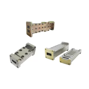
How Waveguide Duplexers Separate Signals
The fundamental challenge in any shared-antenna system is preventing the high-power transmit signal, which can be 1 million times stronger (60 dB) than the faint incoming receive signal, from overwhelming and permanently damaging the receiver circuitry. Waveguide duplexers solve this problem not with complex electronics, but with precise physical engineering, acting as ultra-selective frequency-specific gatekeepers. They are designed to handle power levels from 100 watts (W) to several megawatts (MW) in radar systems, achieving a critical balance where insertion loss for the transmit path is kept below a typical 0.3 dB (ensuring over 93% power efficiency), while providing receiver isolation often exceeding 100 dB. This performance is why they are the default choice in critical infrastructure, from 5G base stations operating in the 3.5 GHz band to air traffic control radars scanning at 2.7 GHz to 2.9 GHz.
A standard commercial duplexer for a 4 GHz system might contain 4 to 6 resonant cavities per path, each tuned to a specific frequency with an accuracy of ± 0.0001% (± 1 kHz at 4 GHz). The transmit and receive signals are often separated by a minimum frequency gap (guard band) of 50 MHz to 200 MHz, though advanced designs can handle gaps as low as 20 MHz.
| Parameter | Typical Value Range | Key Impact |
|---|---|---|
| Frequency Separation | 20 MHz – 200 MHz | Determines how close Tx/Rx frequencies can be |
| Isolation | 90 dB – 120 dB | Protects receiver from transmitter power |
| Insertion Loss | 0.1 dB – 0.5 dB | Directly impacts system power efficiency and range |
| Power Handling | 1 kW – 100 kW (avg.) | Defines application (e.g., cellular vs. radar) |
| Operating Bandwidth | 10 MHz – 80 MHz | Defines the amount of spectrum it can process |
| Temperature Stability | ± 0.0005% / °C | Ensures performance from -40°C to +85°C |
For a 5.8 GHz cavity, the critical internal dimension might be machined to a tolerance of just ±5 micrometers (µm) to ensure peak performance. This precision ensures that the transmit filter presents a low-impedance path (e.g., < 0.1 VSWR) for its specific frequency band, allowing 99% of the energy to pass toward the antenna with minimal loss. Simultaneously, it presents an extremely high-impedance path (blocking > 99.9999% of power) to the receive frequency, forcing that signal to take the only other available path—a similarly tuned filter branch leading directly to the receiver port.
This process is entirely passive and bidirectional, working with 99.9% reliability over an operational lifespan often exceeding 15 years. The entire assembly is typically made from aluminum 6061 or copper, often with a silver plating 3 µm to 5 µm thick to reduce resistive (Ohmic) losses, which can save 5% to 8% in overall system power consumption compared to unplated components. This direct translation of physical design into RF performance is what makes waveguide duplexers uniquely reliable and efficient for high-power applications.
Key Components Inside the Duplexer
The performance of a unit handling 2.5 kW of average power at 10 GHz is entirely governed by the material selection, dimensional accuracy (often within ±15 micrometers), and surface finish (typically better than 0.8 µm Ra) of these components. The primary goal is to minimize Insertion Loss, which directly translates to preserving system efficiency; every 0.1 dB of loss avoided equates to saving over 2.3% of transmitted power, a critical factor in large-scale cellular or radar deployments.
| Component | Primary Function | Key Specifications & Impact |
|---|---|---|
| Resonant Cavities | Filter specific frequencies | Q-factor of 5,000-15,000 determines filter sharpness and loss. |
| Coupling Iris/Irises | Control energy transfer between cavities | Aperture size (e.g., 4.2 mm x 11.5 mm) dictates bandwidth. |
| Main Waveguide Body | Guides electromagnetic waves | 6061 Aluminum with 5 µm silver plating reduces surface resistance. |
| Input/Output Ports | Connect to transmitter, receiver, antenna | WR-75 or WR-90 flange standards ensure interoperability and low VSWR (<1.05). |
| Tuning Screws/Posts | Fine-adjust resonant frequency | Precision-machined from brass, allowing ±0.5 MHz frequency tweaks. |
For a cavity tuned to 3.6 GHz, the critical length might be 20.83 mm. The number of cavities directly impacts performance; a 4-cavity filter might provide 60 dB of rejection at 50 MHz away from the center frequency, while a 6-cavity filter could achieve 85 dB at the same offset, drastically improving isolation. The unloaded Q-factor (Quality Factor) is a measure of how lossy the cavity is. A high Q-factor of 10,000 means energy at the resonant frequency circulates 10,000 times before decaying, resulting in very low insertion loss (< 0.2 dB) and extremely sharp filter skirts.
The size and shape (e.g., circular, rectangular, or elliptical) of a 3.2 mm thick iris are calculated to control the amount of energy transferred between cavities, which sets the filter’s bandwidth. A larger iris creates stronger coupling and a wider bandwidth (e.g., 40 MHz), while a smaller one results in weaker coupling and a narrower bandwidth (e.g., 15 MHz). The entire assembly is housed in a main waveguide body, typically machined from a single block of aluminum 6061 to ensure thermal stability across an operating range of -55°C to +125°C. The interior is often plated with 5 µm of silver, which improves electrical conductivity, reducing resistive losses by ~8% compared to raw aluminum.
Common Uses in Radar and Cellular
In a typical airport surveillance radar (ASR) system, a duplexer might be handling peak transmit powers of 1 MW (megawatt) at a frequency of 2.7 GHz to 2.9 GHz, while providing the necessary >100 dB isolation to protect the receiver from being damaged. In the cellular world, a 5G base station operating in the 3.5 GHz band (n78) uses a smaller, but equally precise, duplexer to manage 200 W of power and enable simultaneous data upload and download, supporting thousands of user connections with a latency of less than 10 ms. The ability to use a single antenna for both functions saves telecom operators significant capex and opex, reducing site rental and maintenance costs by an estimated 15-20% per tower.
A long-range air traffic control radar might have a pulse repetition frequency (PRF) of 1000 Hz, sending out a powerful 5 µs long pulse. The duplexer must switch within a few microseconds to allow the same antenna to listen for the faint returning echo, which can be over 120 dB weaker than the transmitted pulse. The component’s high power handling capacity, often rated for average powers of 5 kW to 10 kW, and its low insertion loss (< 0.3 dB) are vital for maximizing the radar’s detection range, which can exceed 250 nautical miles (approx. 460 km). The physical size and weight of these radar duplexers are less constrained, often occupying a volume of 5-10 liters and weighing over 8 kg, as they are housed in fixed ground-based installations or on large naval vessels.
In contrast, cellular base stations demand a different set of optimizations. Here, the focus is on compact size, weight under 2.5 kg, and cost-effective mass production to deploy across thousands of sites. A duplexer for a 4G/LTE or 5NR base station sector radio must operate within a strictly licensed frequency band, such as 700 MHz with a 45 MHz bandwidth or 3.5 GHz with a 100 MHz bandwidth. The primary performance metrics are isolation (> 90 dB) to prevent receiver desensitization and low loss to preserve Power Amplifier (PA) efficiency, which directly translates to lower electricity bills for the operator.
The internal resonant cavities are manufactured to extremely tight dimensional tolerances of ±20 µm to ensure consistent performance across an operating temperature range of -40°C to +65°C. The mean time between failures (MTBF) for these units is typically calculated in the hundreds of thousands of hours, ensuring a service life of 10-15 years with minimal maintenance, which is essential for minimizing network downtime and operational expenses.
Advantages Over Other Duplexer Types
For instance, in a high-power C-band radar system transmitting 500 kW peaks, a waveguide duplexer’s insertion loss of merely 0.15 dB allows over 96.5% of the transmitted power to reach the antenna, directly increasing range and efficiency. This compares to a typical 0.4 dB loss (over 91% efficiency) in a high-quality cavity filter design, which translates to a significant 5.5% difference in radiated power. This marginal gain is critical; for a radar system, it can mean the difference between detecting a target at 250 km versus 240 km. Furthermore, their exceptional 110 dB isolation ensures the sensitive receiver is protected, a figure that is 15-20 dB better than what many alternative technologies can reliably provide in high-power environments.
| Feature | Waveguide Duplexer | Cavity Filter Duplexer | Ceramic Resonator Duplexer |
|---|---|---|---|
| Typical Insertion Loss | 0.1 dB – 0.3 dB | 0.3 dB – 0.6 dB | 0.8 dB – 1.5 dB |
| Isolation Performance | 90 dB – 120 dB | 70 dB – 90 dB | 50 dB – 80 dB |
| Avg. Power Handling | 5 kW – 50 kW | 1 kW – 5 kW | 100 W – 500 W |
| Operating Frequency | 2 GHz – 110 GHz | 500 MHz – 6 GHz | 700 MHz – 4 GHz |
| Unloaded Q-factor | 8,000 – 20,000 | 3,000 – 6,000 | 1,000 – 2,000 |
| Size/Volume for a 3.5 GHz unit | ~5 liters / 8 kg | ~3 liters / 4 kg | ~0.5 liters / 0.8 kg |
| Cost Factor | High (3x – 5x) | Medium (1.5x) | Low (1x) |
| Temp. Stability (± ppm/°C) | ± 1 – 3 | ± 5 – 10 | ± 15 – 30 |
| Typical Lifespan | 20+ years | 15 years | 10 years |
Waveguide resonators achieve exceptionally high Q-factors of 12,000 to 15,000 at 10 GHz, which is approximately 3 to 4 times higher than what is possible with coaxial cavity filters. This high Q-factor directly enables their superior insertion loss and phenomenal selectivity, allowing them to separate frequencies that are very close together. Their power handling capability is unmatched; a unit with a 30 cm² internal cross-section can handle average power levels of 25 kW and manage voltage gradients that would cause breakdown in smaller, more congested coaxial filters.
While their initial unit cost is higher, often 5,000 compared to 1,200 for a ceramic duplexer, their total cost of ownership over a 15-year lifecycle can be lower for demanding applications. This is due to their exceptional durability, with a mean time between failures (MTBF) exceeding 500,000 hours, and minimal need for recalibration. Their performance is also incredibly stable across a vast operational temperature range (-55°C to +85°C), with a frequency drift of less than ±50 kHz over the entire range, a critical feature for outdoor deployments on tower sites where temperature swings can be 40°C in a single 24-hour cycle. The primary trade-off is size and weight; a waveguide duplexer for a 5.8 GHz system might be 400 mm long and weigh 6 kg, whereas a comparable ceramic block duplexer could be 90% smaller in volume and 80% lighter. Therefore, the choice ultimately hinges on the application’s priority: absolute electrical performance and robustness (waveguide) versus compact size and lowest upfront cost (ceramic).
Installation and Maintenance Basics
For a standard unit operating at 3.5 GHz, proper installation ensures the insertion loss remains below its specified 0.25 dB threshold, preserving over 94% of your transmitted power. A single improperly torqued connector can increase the Voltage Standing Wave Ratio (VSWR) to above 1.5:1, reflecting over 4% of your power back into the transmitter, potentially causing damage over time. Preventative maintenance, conducted at 12 to 18-month intervals, is far more cost-effective than a full replacement, which for a high-power radar duplexer can cost 40,000 and require 8 to 12 hours of system downtime.
- Precision Torque: Always use a calibrated torque wrench. Flange bolt torque is critical and typically must be set to a precise 25-30 inch-pounds (2.8-3.4 Nm). Under-torquing can lead to RF leakage (> -90 dBc) and ingress of moisture, while over-torquing can warp the flange and create a 0.1 dB to 0.3 dB increase in insertion loss.
- Alignment: The waveguide flanges must be perfectly aligned. A misalignment of just 0.5 mm can cause a 0.15 dB increase in loss and dramatically increase the VSWR above 1.8:1, creating hot spots.
- Environmental Sealing: After connecting, apply a specified environmental sealant (e.g., RTV silicone rated for -55°C to 200°C) around the flange interface to prevent moisture ingress, which can cause internal corrosion and increase loss by up to 0.5 dB over a 6-month period in humid climates.
- Regular Inspection: During maintenance, inspect the interior for any signs of corrosion pitting or contamination. Even a thin layer of dust or oxide can increase surface resistance. A professional cleaning with solvents like isopropyl alcohol and a lint-free cloth can restore 99% of performance.
- Performance Testing: Use a calibrated vector network analyzer (VNA) to measure S-parameters. Check that insertion loss is within 0.05 dB of the baseline and isolation remains above 90 dB. A shift of more than 0.1 dB or a 5 dB drop in isolation indicates potential internal issues requiring investigation.
A 15 kg duplexer mounted on a tower requires robust bracketing to avoid stress on the flanges; even a 1 mm deflection can impair performance. Cyclic temperature changes from -30°C to +60°C cause metal to expand and contract, so mounting should allow for slight thermal movement without imparting strain. After physical installation, the electrical alignment must be verified. This involves checking the center frequency and bandwidth with the VNA. The resonant frequency might drift -50 kHz/+100 kHz over the operational temperature range, but it should remain within the system’s allowable +/- 200 kHz tolerance. A final power test should gradually ramp up to 50%, then 100% of operational power (e.g., 2 kW) while monitoring for heating or arcing. Following these procedures, a proper installation can be completed in under 3 hours by a two-person team, ensuring the unit operates reliably for its entire 20-year design life with only bi-annual 2-hour maintenance checks.


