Yagi antennas are directional, with a driven element, reflector, and directors, offering 10–15dBi gain at 2.4GHz for focused point-to-point links. Omni antennas radiate uniformly horizontally (2–5dBi gain), suited for area coverage; Yagi typically operates 400MHz–6GHz, Omni 30MHz–6GHz, differing in pattern and use case.
Table of Contents
How They Send and Receive Signals
A Yagi antenna, like a flashlight, focuses all its energy in a single, narrow beam. This concentrated energy can travel much farther, often reaching distances over 10 miles in ideal, unobstructed conditions for a typical 14-16 dBi gain model. In contrast, an Omni antenna radiates its signal in a 360-degree horizontal pattern, much like a light bulb illuminates a room evenly in all directions. However, this comes at the cost of range; the signal strength is distributed in all directions, so its effective range is typically limited to 1-3 miles for a standard 5-6 dBi gain antenna mounted on a roof.
The physical length and spacing of these elements are meticulously calculated, often to within millimeter precision, to resonate at a specific frequency, such as 2.4 GHz or 5 GHz for Wi-Fi. This structure allows it to focus over 90% of its transmitted energy into a very narrow beam, typically with a horizontal beamwidth of 60 to 80 degrees. This high forward gain, often between 10 to 15 dBi for consumer models, means it can pick up extremely faint signals from a specific direction while rejecting unwanted interference from the sides or rear. For instance, when receiving a signal, the elements work together to capture and concentrate the radio waves onto the driven element, achieving a signal-to-noise ratio improvement that can be 5 to 10 times better than an Omni in the targeted direction.
Conversely, the classic Omni antenna, often a simple vertical whip or collinear design, has no such directional preference. Its internal elements are arranged to create a symmetrical, doughnut-shaped radiation pattern. While its vertical beamwidth is usually narrow (around 10-15 degrees to push the signal outward, not straight up), the horizontal coverage is a perfect circle. This makes it ideal for covering a large, open-floor office of 3000 square feet or providing general coverage around a 50-foot mast. However, because it must distribute its 5 dBi of power evenly across the entire horizon, the power density in any single direction is significantly lower. This is why its range is inherently shorter; the signal strength decays more rapidly with distance. A key performance metric is the VSWR (Voltage Standing Wave Ratio), which for a well-designed Omni should be below 1.5:1 across its operating band, ensuring over 95% of the power from the router is actually radiated without being reflected back, which is crucial for efficiency.
| Parameter | Yagi Antenna | Omni Antenna |
|---|---|---|
| Typical Gain | 10 – 15 dBi (or higher) | 3 – 6 dBi (common for Wi-Fi) |
| Horizontal Beamwidth | Narrow (30° – 80°) | 360° (Full Circle) |
| Key Strength | Long-range links (>10 mi) | General area coverage |
| Signal Capture | Highly selective from one direction | Receives from all directions equally |
| Best For | Connecting two fixed points (e.g., building to building) | Covering a central area (e.g., a house or camp) |
A Yagi is unparalleled for pulling in a weak -90 dBm signal from a specific internet service provider’s tower 8 miles away, effectively ignoring competing signals. An Omni, however, is the default choice for a home router because it needs to serve multiple devices—a laptop, phones, smart TVs—scattered throughout the building in all directions, even if its effective range through walls may drop to 1500 square feet.The gain figure can be misleading; a 9 dBi Omni doesn’t have more power than a 6 dBi one, it simply squeezes the radiation pattern to be flatter, trading vertical coverage for slightly more horizontal reach, which is why height placement is critical. For a reliable link, the polarization (usually vertical for Omni) must also match between the transmitting and receiving antennas; a mismatch can introduce over 20 dB of loss, completely negating any gain advantage.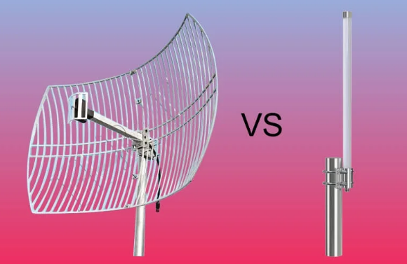
Directional vs. 360-Degree Coverage
A high-gain 14 dBi Yagi might project a signal that remains usable at 15 miles, but only within a narrow 45-degree arc. Meanwhile, a 6 dBi Omni antenna effectively blankets a 360-degree area with a radius of roughly 1-2 miles, but its signal strength at the 2-mile mark will be vastly weaker than the Yagi’s focused beam at the same distance.
| Parameter | Directional (Yagi) Antenna | Omnidirectional Antenna |
|---|---|---|
| Coverage Shape | Narrow Beam (30° – 80°) | Full 360° Circle |
| Best Use Case | Point-to-Point links | Point-to-Multipoint coverage |
| Ideal Range | Long (>10 mi) | Short to Medium (1-3 mi) |
| Interference Rejection | High (from sides/rear) | Low (receives all noise) |
| Installation Complexity | High (must be aimed) | Low (mount vertically) |
A typical Wi-Fi Yagi for 5 GHz might have a 50-degree horizontal beamwidth and a 40-degree vertical beamwidth. This means you must aim it with an accuracy of within ±25 degrees horizontally and ±20 degrees vertically towards the target; a misalignment beyond this ±20-degree window can easily result in a 3 dB signal loss, cutting your received signal strength in half. This precise focus is why Yagis are unmatched for connecting two fixed points, like linking your house to a friend’s 8 miles away, achieving a stable -70 dBm signal level where an Omni might only see -90 dBm (essentially unusable). The focused beam also provides 10 to 15 dB of rejection to interference sources coming from the sides or rear, which dramatically cleans up the signal and improves the signal-to-noise ratio (SNR).
In stark contrast, the Omni antenna’s coverage resembles a donut or life preserver pattern. Its signal is radiated equally in all horizontal directions, creating a coverage circle on the ground. However, this circle’s diameter is highly dependent on the installation height. Mounting a 5 dBi Omni antenna at 20 feet versus 10 feet can increase its effective coverage area from about 12,500 sq ft to over 50,000 sq ft due to reduced ground absorption and obstruction. The critical trade-off is that its gain is achieved by “squeezing” this donut, making it flatter. A 9 dBi Omni doesn’t have more power than a 5 dBi model; it has a narrower vertical beamwidth (e.g., 8 degrees vs. 15 degrees).
Best Uses for Each Antenna Type
A 30 omni antenna will fail to establish a stable 8-mile link. The decision tree starts with a simple question: do you need to connect two specific points, or cover a broad area? The answer dictates everything, from the initial investment and installation labor time to the long-term network performance and throughput stability. Using the wrong type can result in a 50% or greater loss in potential speed and reliability, making the correct application paramount.
- Yagi-Uda Antenna: Use for long-distance, point-to-point links where the target location is fixed and known.
- Omnidirectional Antenna: Use for general coverage in a surrounding area where client devices (phones, laptops) are mobile and scattered.
The Yagi antenna is the specialist tool, engineered for one primary task: maximizing signal strength over a long distance in a single, precise direction. Its value is realized in scenarios like Wireless Internet Service Provider (WISP) backhauls, where a sector antenna on a tower might connect to a subscriber’s home 5 miles away using a Yagi with a 15 dBi gain, enabling a 100 Mbps connection that would otherwise be impossible. A rural homeowner aiming to receive internet from a tower 12 miles away would use a Yagi, carefully aligned within a ±5-degree margin to achieve a stable received signal strength of -78 dBm. They are also ideal for security camera links, sending a video stream from a remote barn 500 yards from the main house without any data loss. The key metric is the link budget: a Yagi’s high gain directly increases this margin, allowing it to overcome 20-30 dB of path loss that would defeat an omni antenna. The installation is a dedicated process, often requiring a 30-minute alignment procedure with a signal strength meter to peak the reading, but the result is a robust, high-SNR link.
For example, a Yagi is the only practical choice for a point-to-point wireless bridge between two office buildings spaced 2 miles apart, providing a 1 Gbps connection with 99.9% uptime.
Comparing Range and Signal Strength
For instance, a typical 6 dBi gain omni antenna connected to a 100 mW (20 dBm) router might provide a stable -67 dBm signal at 150 feet in an open field, which is sufficient for 50 Mbps throughput on a 5 GHz link. However, a 14 dBi Yagi using the same 100 mW transmitter can achieve that same -67 dBm signal level at over 2,000 feet, because it concentrates all energy into a 40-degree wide beam, dramatically increasing power density in one direction and extending its usable range by 400% or more. This comparison is governed by the FSPL (Free Space Path Loss) equation, where signal strength degrades with the square of the distance; every time distance doubles, signal strength drops by roughly 6 dB.
- Omnidirectional Antenna: Provides shorter-range, uniform coverage in all directions. Signal strength decays rapidly with distance due to energy dispersion.
- Yagi (Directional) Antenna: Provides longer-range, focused coverage in a specific direction. Signal strength is maintained over greater distances due to high forward gain.
Most Wi-Fi radios require a signal strength of at least -82 dBm to maintain a basic 10 Mbps connection and around -65 dBm for a full-speed 300 Mbps link. A 9 dBi omni might struggle to maintain a -75 dBm signal at 500 feet in a semi-obstructed environment, like a neighborhood with light foliage. In contrast, a 14 dBi Yagi aimed precisely can maintain a strong -71 dBm signal at 2,500 feet in the same environment, because its narrow 50-degree beamwidth avoids obstacles and interference that the omni antenna’s 360-degree pattern would inevitably encounter. This makes the Yagi’s effective data rate at distance significantly higher; you might see 80 Mbps versus the omni’s 5 Mbps at the 2,000-foot mark. However, this range advantage is highly dependent on alignment. A Yagi antenna misaligned by just 15 degrees can suffer a 4 dB loss, reducing its effective range by 30%. For the omni, mounting height is the key variable; raising it from 10 feet to 30 feet can extend its clean coverage area from 15,000 sq ft to over 70,000 sq ft by leveraging a clearer Line-of-Sight (LoS) path.
A 2.4 GHz signal passing through two 6-inch interior drywall walls will experience approximately 6 dB of attenuation, effectively halving the signal strength and cutting the reliable range of an omni antenna by 40%. A 5 GHz signal is attenuated even more severely by obstacles. A Yagi antenna can often bypass these issues by being aimed to avoid the worst obstructions, but its performance will be decimated by any object, like a mature tree with dense foliage (15-20 dB loss), directly within its narrow beam path. For ultimate range in a pure Line-of-Sight scenario, a Yagi is unbeatable. But in a cluttered urban or suburban setting, the omni’s ability to provide decent coverage in all directions without precise aiming often makes it the more practical choice for covering a 2,500 sq ft home, even if its peak range is shorter.
Physical Design and Installation
A compact 6 dBi omni antenna might be a simple 18-inch tall, 1.5-pound vertical rod that screws directly onto a router’s external port, requiring just 15 minutes and a simple ½-inch U-bolt mount to install on a mast. Conversely, a high-performance 16 dBi Yagi for 5.8 GHz can be a 48-inch long assembly of 12 precisely spaced aluminum elements weighing over 5 pounds, requiring a robust 2-inch mast clamp and a careful 2-hour installation process involving a compass, GPS, and a signal strength meter to achieve perfect alignment.
- Omnidirectional Antenna: Typically a vertical, cylindrical, or rod-shaped design. Installation is simple, focusing on vertical placement and central location.
- Yagi Antenna: A long, directional array of elements mounted on a horizontal boom. Installation is complex, requiring precise horizontal and vertical aiming.
The most common type is a collinear array, where multiple dipole elements are stacked vertically inside a 1-inch diameter PVC or fiberglass radome. This design creates the characteristic 360-degree horizontal pattern. A typical 2.4 GHz model might be 12 to 24 inches tall, with a base connector requiring 30 lb-in of torque to ensure a weatherproof seal. Mounting is straightforward: it is always oriented vertically and placed as high and centrally as possible. For a 2,500 sq ft home, this might mean mounting it on a 5-foot pole in the attic. For a 50-acre farm, it would be mounted on a 30-foot telescoping mast secured with 3 guy wires to withstand 70 mph winds. The critical installation factor is height; raising the antenna from 10 ft to 30 ft can reduce signal path obstacles by 60%, dramatically improving coverage. The coaxial cable run is a major source of signal loss (attenuation); a run of 50 feet of standard RG-58 cable can lose 6.5 dB of signal at 2.4 GHz, effectively cutting the system’s effective radiated power (ERP) in half.
| Aspect | Omnidirectional Antenna | Yagi Antenna |
|---|---|---|
| Typical Size | Compact (e.g., 18″ H x 1″ Dia) | Long (e.g., 48″ L x 24″ W) |
| Mounting | Vertical mast (U-bolt) | Horizontal boom (mast clamp) |
| Aiming | Non-critical (vertical only) | Critical (azimuth & elevation) |
| Wind Load | Low (0.5 sq ft area) | High (2.5+ sq ft area) |
| Installation Time | 15 – 30 minutes | 1 – 3 hours |
The Yagi antenna is a mechanical engineering challenge. Its performance hinges on the precise spacing between its reflector, driven element, and directors, which are often accurate to within ±1 mm. The entire assembly is mounted on a 1-inch diameter aluminum boom and must be pointed with an accuracy of ±5 degrees or better. This requires a mounting assembly that is both rigid and adjustable. Installers use a heavy-duty galvanized mast clamp capable of supporting 15+ pounds without flexing, attached to a 2-inch OD steel mast. The aiming process is a two-step procedure: first, azimuth (compass direction) is set using a digital compass app, aiming for a bearing of 120 degrees true, for example. Then, elevation tilt is adjusted, often requiring a digital inclinometer to set a +2.5-degree upward angle to account for Earth’s curvature over a 7-mile link.
Choosing for Home or Business Use
For a standard 2,500 sq ft single-family home with a router centrally located, a simple 5 dBi omni antenna costing 40 provides adequate coverage, delivering a -67 dBm signal strength in most rooms and supporting 20+ devices streaming at 50 Mbps each. Conversely, a business with a 15,000 sq ft warehouse needs a different solution; a single omni antenna would leave dead zones with -85 dBm signals in the corners, forcing the deployment of 4-6 access points at a cost of 1,200 for hardware and installation. A Yagi antenna, priced between 150, is rarely a whole-property solution but becomes essential for solving specific problems, like bridging a 500-foot gap to a remote security camera or pulling in a distant wireless signal, where its focused gain provides a 10x improvement in data reliability over an omni.
| Consideration | Home Use (e.g., 2,500 sq ft) | Business Use (e.g., 15,000 sq ft Warehouse) |
|---|---|---|
| Primary Antenna Type | Omnidirectional | Mixed (Omni for coverage, Yagi for links) |
| Typical Budget | 50 | 2,000+ |
| Coverage Goal | Uniform -67 dBm throughout | Uniform -70 dBm with no dead zones |
| Key Challenge | Penetrating interior walls (~6 dB loss each) | Covering vast open areas & linking buildings |
| Installation | DIY, 30-minute setup | Professional, 8-16 hour deployment |
The goal is to provide reliable coverage for a multitude of devices—smartphones, laptops, TVs, and IoT sensors—that move randomly throughout a 3-bedroom home. A single, centrally mounted 6 dBi omni antenna can effectively cover 95% of the floor plan, suffering only 10-15 dB of attenuation through drywall, which maintains a usable signal. The total project cost remains under $100, including a mount and 20 feet of low-loss cable, and can be completed in under an hour. The only scenario for a Yagi in a home is if the resident is a remote worker relying on a Fixed Wireless Access (FWA) internet provider whose tower is 5 miles away. In this case, a 14 dBi Yagi meticulously aimed at the cell tower can transform an unstable -93 dBm signal into a robust -78 dBm connection, increasing download speeds from 5 Mbps to 80+ Mbps.
A 50,000 sq ft office space with 40 interior walls cannot be covered by one antenna. The standard solution is a network of 6-8 omnidirectional access points mounted on the 15-foot ceiling, each covering a 40-foot radius and connected via Ethernet back to a main switch. This design ensures that no employee’s device ever drops below -72 dBm, maintaining seamless connectivity for VoIP phones and video conferencing. However, Yagi antennas find critical roles in business infrastructure for point-to-point links. A retail store with a main building and a separate warehouse 800 feet away would use a Yagi at each end to create a wireless bridge.


