A quad-ridged horn antenna typically has a beamwidth of 60-80° in X-band (8-12 GHz), varying with ridge spacing and length; lower bands (e.g., L-band) may reach 90-100°, while higher Ku-band narrows to 50-60°, ideal for satellite communication directional coverage.
Table of Contents
Basic Antenna Beamwidth Explanation
Antenna beamwidth, specifically the Half-Power Beamwidth (HPBW), is the most critical metric for understanding an antenna’s directional focus. It is not a single point but an angular range. Measured in degrees, it defines the cone where the antenna radiates or receives the majority of its power. For instance, a high-gain satellite dish might have a very narrow 3-degree HPBW to focus energy over long distances, while a Wi-Fi router’s antenna might have a wider 120-degree HPBW to provide general coverage in a room. This angular span is defined as the angle between the two points on the antenna’s radiation pattern where the power drops to half (-3 dB) of its maximum value at the peak. This -3 dB point corresponds to a reduction in power density by approximately 50%.
The beamwidth of an antenna is inversely proportional to its physical size relative to the wavelength it operates at. A larger antenna (in terms of wavelengths) will have a narrower, more focused beam.
Key Relationship: Beamwidth ≈ 70° * (Wavelength / Antenna Aperture Width). For a antenna with an aperture of 5 times the wavelength, the beamwidth would be roughly 14 degrees. This formula highlights why low-frequency antennas (long wavelengths) are large for narrow beams, and high-frequency antennas can be small for the same beamwidth.
A narrower beamwidth, say 10 degrees, translates to higher gain (often 20 dBi or more), as energy is concentrated into a smaller area. This is ideal for point-to-point communications linking two buildings 5 km apart. Conversely, a wider beamwidth, like 90 degrees, offers lower gain (around 9 dBi) but broader coverage, perfect for a cell tower sector providing service over a 120-degree arc. The -3 dB points are crucial because they represent the practical, usable range of the antenna where performance is still highly effective. Understanding this fundamental concept is essential for predicting how an antenna will perform in any given application, setting the stage for how the complex structure of a quad-ridged horn manipulates this principle across a wide frequency range.
Quad-ridged horn design overview
A quad-ridged horn antenna is a complex and highly effective design engineered to achieve an exceptionally wide operational bandwidth, often exceeding a 10:1 frequency ratio (e.g., 2 GHz to 20 GHz). Unlike a standard pyramidal horn, its interior features four precisely tapered metallic fins, or ridges, that protrude from the top, bottom, and sidewalls. These ridges are the core of its performance, radically transforming the antenna’s characteristics to support a vast range of applications, from ECM systems requiring rapid frequency hopping to high-resolution spectroscopy scanning across multiple bands. The fundamental trade-off for this immense bandwidth is a physically larger structure compared to a narrowband horn of equivalent gain, often requiring machining tolerances as tight as 0.05 mm to ensure consistent electrical performance across the entire band.
The primary function of the ridges is to meticulously control the waveguide’s characteristic impedance and manipulate the electromagnetic field distribution. As the ridges taper from the throat (the feed point) towards the aperture, they create a gradual transition.
- This forces the E-field to concentrate between the opposing ridge tips, effectively lowering the cut-off frequency of the fundamental propagation mode. This allows the antenna to operate efficiently at frequencies up to 70% lower than a smooth-walled horn of the same physical size.
- Concurrently, the ridges suppress the propagation of higher-order modes that can distort the radiation pattern at higher frequencies, ensuring a stable pattern over the entire bandwidth.
A typical design might feature ridges with a 15-degree taper angle and a 0.3 mm ridge-to-ridge gap at the throat, expanding to a 15 mm gap at the aperture. This precise geometry is what enables the ultra-wideband performance.
The antenna’s overall performance is a direct result of several interdependent geometric parameters:
- Aperture Dimensions: Dictate the lowest usable frequency and minimum gain. A 150 mm x 150 mm aperture might support operation down to 2 GHz.
- Ridge Taper Profile: A longer, more gradual taper (e.g., 200 mm long) improves impedance matching, reducing the Voltage Standing Wave Ratio (VSWR) to below 2:1 across most of the band, but increases the antenna’s total mass by approximately 300 grams.
- Feed Geometry: The initial ridge gap and curvature at the throat are critical for matching the 50-ohm input impedance of the coaxial feed cable, with even a 0.1 mm deviation potentially causing a 10% impedance mismatch at the high-frequency end.
This intricate design results in an antenna that maintains a consistent beamwidth between 60 and 80 degrees and a gain between 10 and 15 dBi across a decade of bandwidth, a feat impossible for simpler antenna designs.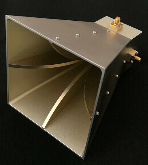
How frequency affects beamwidth
A quad-ridged horn designed to operate from 2 GHz to 20 GHz will exhibit a significant beamwidth variation, typically narrowing from approximately 80 degrees at the lowest frequency to around 25 degrees at the highest frequency. This 70% reduction in angular coverage has major implications for system design, directly influencing coverage area, gain, and pointing accuracy.
The core mechanism behind this change is the effective aperture of the antenna. The aperture’s size is fixed in meters, but its size in terms of wavelengths changes dramatically with frequency.
- At a low frequency like 2 GHz (wavelength λ = 150 mm), an antenna with a 150 mm aperture is only about 1 wavelength wide. This electrically small size results in a wide, diffused beam pattern.
- At a high frequency like 20 GHz (λ = 15 mm), the same 150 mm aperture becomes 10 wavelengths wide. This electrically large aperture can form a much more focused, narrower beam.
This relationship is often summarized by the formula: Beamwidth (in degrees) ≈ k * (λ / D), where k is a constant (typically between 50 and 70 depending on the aperture illumination), λ is the wavelength, and D is the aperture diameter. For a quad-ridged horn, the presence of the ridges modifies this formula slightly but the inverse relationship remains absolute.
The following table illustrates this dramatic change for a theoretical quad-ridged horn with a 150 mm x 150 mm aperture:
| Frequency (GHz) | Wavelength (mm) | Aperture Size (in Wavelengths) | Typical Beamwidth (Degrees) | Approximate Gain (dBi) |
|---|---|---|---|---|
| 2 | 150 | 1.0 x 1.0 λ | 70 – 80 | 9 – 11 |
| 6 | 50 | 3.0 x 3.0 λ | 25 – 30 | 15 – 17 |
| 18 | 16.7 | 9.0 x 9.0 λ | 20 – 25 | 20 – 22 |
A 10 dB increase in gain (from ~11 dBi to ~21 dBi) as the beam narrows is a direct trade-off; you get a stronger, more focused signal at higher frequencies but must aim the antenna more precisely, as a 1-degree alignment error at 20 GHz will cause a significantly greater signal loss than the same error at 2 GHz. This dictates the required accuracy for a positioning system, which might need to be better than ±0.5 degrees for high-frequency operations.
Measuring beamwidth accurately
Accurately measuring the beamwidth of a quad-ridged horn antenna requires a controlled laboratory environment, typically an anechoic chamber lined with pyramidal RF absorber foam that provides 40 dB to 50 dB of reflectivity reduction. The setup involves mounting the antenna under test on a precision positioner capable of ±0.1-degree angular resolution and rotating it while a fixed reference antenna, often a standard gain horn, measures the transmitted signal strength. The received power is recorded in 1-degree or 0.5-degree increments across a full 180-degree sweep to capture the main lobe and minor side lobes. The resulting data plot, called a radiation pattern, is used to pinpoint the exact angles where the power drops to half (-3 dB) of its maximum value. The angular distance between these two -3 dB points is the Half-Power Beamwidth (HPBW). For a high-frequency antenna operating at 20 GHz, a 1-degree measurement error in this process can lead to a 5% miscalculation in gain, underscoring the need for meticulous precision.
The integrity of the measurement hinges on satisfying the far-field condition, which states that the distance between the two antennas must be greater than 2D²/λ, where D is the largest dimension of the antenna aperture and λ is the wavelength. For a 150 mm aperture antenna at 10 GHz (λ = 30 mm), the minimum required distance is 2 * (0.15)² / 0.03 = 1.5 meters. Measurements taken closer than this distance will be inaccurate due to spherical wavefront interactions.
- Calibration: The entire measurement system, including cables and connectors, must be calibrated with a reference antenna of known gain (e.g., 15 dBi ± 0.2 dB) to remove systematic errors. A 0.5 dB calibration error directly translates into a 6% error in calculated gain.
- Sampling Density: The angular step size must be small enough to accurately define the pattern’s slope. A common rule is to sample at intervals smaller than one-tenth of the expected beamwidth. For an expected 25-degree beamwidth, a 2.5-degree step is the absolute maximum, but a 1-degree step is preferred for higher accuracy.
- Signal-to-Noise Ratio (SNR): The measurement system must have a high dynamic range to clearly distinguish the -3 dB points from the noise floor. A minimum 30 dB SNR is recommended at the -3 dB points to ensure a measurement precision of better than ±0.5 degrees.
The following table outlines key parameters for a reliable beamwidth measurement across different frequencies for a fixed aperture antenna:
| Frequency (GHz) | Wavelength (mm) | Min. Far-Field Distance (m) | Recommended Angular Step Size (Degrees) | Acceptable Amplitude Error (dB) |
|---|---|---|---|---|
| 2 | 150 | 0.75 | 5.0 – 7.0 | ±0.3 |
| 6 | 50 | 2.25 | 2.0 – 3.0 | ±0.2 |
| 18 | 16.7 | 6.70 | 0.5 – 1.0 | ±0.1 |
Environmental factors like multipath reflections from chamber walls or the support structure can corrupt data. These are minimized by using low-density foam supports and time-domain gating if available. The final measured beamwidth should be an average of multiple E-plane and H-plane cuts, with the standard deviation between measurements typically falling within ±1 degree for a well-conducted test. This rigorous process ensures the reported beamwidth value is a reliable predictor of the antenna’s real-world performance.
Comparing with other antenna types
The quad-ridged horn occupies a unique niche by offering an exceptionally wide 10:1 operational bandwidth (e.g., 2 GHz to 20 GHz), a feat unmatched by most other common antenna designs. This performance comes at a premium: a commercial-off-the-shelf quad-ridged horn can cost 8,000, significantly more than a standard gain horn or a double-ridged guide antenna. Its physical size is also substantial, with a typical unit for this frequency range measuring roughly 250 mm in length and weighing over 1.5 kg.
A typical X-band horn might operate from 8 GHz to 12 GHz, a 4 GHz bandwidth, with a consistent 20 dBi gain and a stable 15-degree beamwidth. Its construction is simple, leading to a lower cost of 1,200 and a lighter weight of under 500 grams. However, to cover the same spectrum as a quad-ridged horn, you would need an array of 5 to 7 individual standard horns, a solution that is mechanically cumbersome and electronically complex to switch between. A double-ridged horn offers a middle ground, providing a wider 5:1 bandwidth (e.g., 4 GHz to 20 GHz) and a lower cost of 4,000, but it often suffers from higher cross-polarization levels, typically -15 dB compared to the quad-ridge’s -20 dB, and less symmetrical patterns.
A discone antenna can cover a 10:1 bandwidth with a nearly omnidirectional pattern, but its gain is very low, typically -2 dBi to +3 dBi, making it unsuitable for directed energy or long-range sensing. An LPDA offers higher directivity, with gains around 8 dBi, but its beamwidth is highly frequency-dependent, shifting from 80 degrees at a low frequency to 40 degrees at a high frequency, and its front-to-back ratio can degrade to 10 dB at band edges.
The quad-ridged horn maintains a more consistent front-to-back ratio of >20 dB across its entire range. The ultimate trade-off is between the quad-ridge’s 70% higher cost and 50% greater mass versus a double-ridge horn for the benefit of its 30% wider instantaneous bandwidth, superior pattern symmetry, and enhanced polarization isolation, metrics that are critical for precision electronic warfare and radar warning receiver systems where a single antenna must perform a multitude of functions simultaneously without any performance gaps.
Practical use case examples
Its 10:1 frequency ratio allows a single antenna to replace an entire array of narrower-band devices, simplifying system architecture and reducing lifecycle costs. In a practical defense electronic countermeasures (ECM) suite, a single quad-ridge horn covering 2 GHz to 20 GHz can be used to identify, jam, and analyze threats, a task that would otherwise require switching between 5 or 6 different antenna types. This eliminates a critical 500-microsecond delay associated with RF switching, ensuring instantaneous response. The antenna’s typical 50 dB isolation between ports and -20 dB cross-polarization level are essential for maintaining signal integrity in these dense electromagnetic environments.
| Application | Key Performance Parameters | Quad-Ridge Horn Value | Alternative Solution & Drawback |
|---|---|---|---|
| EW/ECM Suite | Frequency Agility, Power Handling | 2-20 GHz instant bandwidth, handles 500 W peak power | Bank of 5 horns: +15% cost, +300% weight, 500 µs switch delay |
| EMC Compliance Testing | Scan Speed, Dynamic Range | 1-18 GHz continuous sweep, 80° beam for wall-to-wall coverage | LPDA: Gain drops to -2 dBi at low freq, 30% slower scan time |
| Satellite Comm (Ground) | Gain Flatness, Polarization Purity | Gain 12±1.5 dBi from 4-18 GHz, axial ratio <3 dB | Two separate horns: Requires complex mechanical polarizer |
| Imaging & Spectroscopy | Beam Consistency, VSWR | Beamwidth 60°±10° across band, VSWR <2.5:1 | Reflector: Suffers from sidelobe degradation (>-10 dB) at high freq |
In a commercial electromagnetic compatibility (EMC) testing chamber, the antenna is mounted on a robotic mast that scans a 3D volume of a 10m x 5m x 3m room. The antenna’s 80-degree beamwidth at lower frequencies ensures uniform illumination of large equipment like a 2.5m server rack, while its narrower 25-degree beam at higher frequencies provides the resolution needed to pinpoint emissions from a 5cm circuit board trace. This allows for a complete 1 GHz to 18 GHz compliance scan to be completed in under 30 minutes, a task that would take over 90 minutes with a slower-cycling antenna like a log-periodic. The antenna’s VSWR below 2:1 across the band ensures maximum power transfer from the 1000 W amplifier, preventing costly retests due to insufficient field strength.
A single antenna can maintain a 12 dBi gain with less than 1.5 dB of ripple across the entire 4 GHz to 18 GHz military Ka-band and Ku-band spectrum. This gain flatness is critical for maintaining a stable link margin and a bit error rate better than 10e-12 without requiring constant power adjustment. The antenna’s inherent design provides >25 dB of port-to-port isolation, enabling the simultaneous transmission and reception of orthogonal polarizations without a dedicated, lossy external duplexer. This translates to a 3 dB improvement in system noise figure, which can extend the reliable communication range by approximately 20% for a UAV operating at a 50 km distance. While the initial unit cost is high (~$7,000), it eliminates the need for multiple antennas and RF components, resulting in a 40% reduction in system integration costs and a more reliable platform over a 15-year operational lifespan.


