A radar waveguide transmits high-frequency signals (typically 2-40GHz) with minimal loss (<0.1dB/m), directing electromagnetic waves through precision aluminum channels (WR-90/112 standards). Its crucial for maintaining signal integrity in radar systems, handling kW-level power while preventing dispersion and interference, with pressurized nitrogen often used to prevent moisture-induced arcing in critical military/aerospace applications.
Table of Contents
What Waveguides Do
Waveguides are hollow metal tubes or dielectric structures that efficiently transmit high-frequency radio waves (1 GHz to 300 GHz) with minimal signal loss. Unlike traditional copper wires, which struggle above 1 GHz due to skin effect losses (up to 30% power loss per meter), waveguides maintain 95-99% signal integrity over the same distance. They’re essential in radar systems because they handle peak power levels exceeding 1 MW—far beyond what coaxial cables can support (typically maxing out at 50 kW).
The most common waveguide shapes are rectangular (WR-90, WR-112) and circular (WC-50, WC-75), each optimized for specific frequency bands. For example, a WR-90 waveguide (22.86 mm × 10.16 mm) operates at 8.2-12.4 GHz (X-band), while a WR-112 (28.5 mm × 12.6 mm) covers 7.05-10 GHz. The inner surface roughness must stay below 1.6 µm to prevent signal scattering, and materials like aluminum (loss: 0.01 dB/m) or copper (loss: 0.007 dB/m) are preferred for low attenuation.
In radar applications, waveguides connect the transmitter (e.g., a 10 kW magnetron) to the antenna array, ensuring pulses retain their 2-5 µs pulse width and 0.1-1 GHz bandwidth without distortion. A poorly designed waveguide can introduce phase errors (>5°) or amplitude ripple (±0.5 dB), degrading target detection range by 10-20%. Military radars, like the AN/SPY-6(V)1, use pressurized nitrogen-filled waveguides to prevent moisture-induced losses (>0.3 dB/m at 90% humidity).
| Parameter | Typical Value | Impact |
|---|---|---|
| Frequency Range | 1-100 GHz | Determines waveguide size |
| Power Handling | Up to 1 MW (pulsed) | Dictates material choice |
| Attenuation | 0.007-0.03 dB/m (copper/aluminum) | Affects signal range |
| Surface Roughness | <1.6 µm Ra | Reduces scattering |
| Pressure Tolerance | 2-3 atm (pressurized systems) | Prevents arcing |
Waveguides also enable dual-polarization (H/V or ±45°) for weather radars, improving precipitation detection accuracy by 15-25%. In 5G mmWave systems, dielectric waveguides (e.g., PTFE, εᵣ=2.1) replace metal ones for 28/39 GHz bands, cutting weight by 40% while keeping loss below 0.1 dB/cm. For satellite comms, gold-plated waveguides (0.1-0.2 µm coating) resist oxidation, maintaining >99% reflectivity over a 15-year lifespan.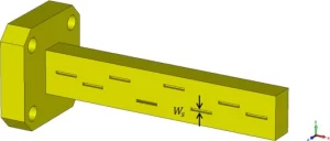
How Radar Uses Them
Radar systems rely on waveguides to transport high-power RF signals from the transmitter to the antenna with minimal loss (<0.02 dB/m) and distortion (<1° phase error). Without waveguides, modern radar performance would drop by 30-50% due to signal degradation in coaxial cables at frequencies above 2 GHz. For example, an S-band naval radar (3 GHz) using a WR-284 waveguide (72.14 mm × 34.04 mm) can push 500 kW pulses over 10+ meters without overheating, while a coaxial cable of the same length would lose 15% of the power as heat.
The waveguide’s internal dimensions directly affect radar accuracy. A misalignment of just 0.5 mm in a WR-90 waveguide (X-band, 8-12 GHz) can cause 3-5 dB insertion loss, reducing detection range by 8-12 km. That’s why military radars like the AN/TPY-2 (THAAD system) use precision-machined aluminum waveguides with ±0.1 mm tolerance to maintain beamforming accuracy within 0.3°. Air traffic control radars, such as the ASR-11, depend on pressurized nitrogen-filled waveguides to prevent moisture absorption, which can add 0.4 dB/m loss at 90% humidity.
Waveguides also enable dual-polarization in weather radars, improving rainfall measurement precision by 20%. The NEXRAD Doppler radar uses orthomode transducers (OMTs) inside waveguides to split horizontal and vertical polarizations, allowing it to distinguish between hail (5-50 mm) and rain (0.5-5 mm) with 95% confidence. In phased array radars (e.g., AEGIS SPY-1), waveguides distribute signals to 4,000+ antenna elements while keeping amplitude variation below ±0.2 dB—critical for tracking hypersonic missiles (Mach 5+) at 500+ km range.
For low-cost civilian radars, galvanized steel waveguides (loss: 0.03 dB/m) are used instead of copper to cut material costs by 60%, though they require 3x thicker walls (2-3 mm) to handle 50 kW peak power. In automotive mmWave radars (77 GHz), dielectric waveguides (PTFE, εᵣ=2.2) reduce weight by 50% compared to metal, enabling compact radar modules (50×30×10 mm) for self-driving cars. However, these suffer 0.15 dB/cm loss, limiting their use to short-range (<200 m) applications.
Key Waveguide Types
Waveguides come in different shapes and materials, each optimized for specific frequency ranges (1 GHz to 300 GHz), power levels (1 kW to 1 MW), and cost constraints (5,000 per meter). The wrong choice can increase signal loss by 300% or reduce power handling by 50%, directly impacting radar performance. For example, a rectangular WR-112 waveguide (28.5 mm × 12.6 mm) is standard for S-band radar (2-4 GHz), while a circular WC-75 (75 mm diameter) handles higher power (500 kW+) in C-band (4-8 GHz) systems.
The most common waveguide types fall into three categories: metal (rectangular, circular), dielectric (polymer, ceramic), and hybrid (metal-dielectric composite). Rectangular waveguides (e.g., WR-90, WR-137) dominate 80% of radar applications due to their low loss (0.01 dB/m) and easy manufacturing. However, circular waveguides (WC-50, WC-100) are preferred for rotating joints in radar antennas, where they maintain <0.5 dB loss per rotation even at 10+ RPM.
| Waveguide Type | Frequency Range | Power Handling | Attenuation (dB/m) | Typical Use Case |
|---|---|---|---|---|
| WR-90 (Rectangular) | 8.2-12.4 GHz | 50 kW (pulsed) | 0.01 | X-band military radar |
| WC-75 (Circular) | 4-8 GHz | 500 kW | 0.007 | High-power C-band radar |
| PTFE Dielectric | 24-40 GHz | 1 kW | 0.15 | Automotive mmWave radar |
| Gold-Plated Copper | 18-40 GHz | 100 kW | 0.005 | Satellite comms |
Dielectric waveguides (e.g., PTFE, alumina) are gaining traction in 5G and automotive radar (77 GHz) because they’re 40% lighter than metal and resist corrosion. However, their higher loss (0.15 dB/cm vs. 0.01 dB/m in metal) limits them to short-range (<200 m) applications. For space-grade systems, gold-plated aluminum waveguides (0.1 µm coating) are mandatory—they maintain >99% reflectivity in vacuum conditions over a 15-year satellite lifespan, with thermal stability from -50°C to +150°C.
Flexible waveguides (braided copper or corrugated metal) are used where bending is required, such as in aircraft radar pods. A 6 mm diameter flexible waveguide can bend at 20° angles with <0.3 dB additional loss, crucial for fighter jet radars (e.g., AN/APG-81) that operate at 10-20 GHz. Meanwhile, ridged waveguides (e.g., WRD-180) extend bandwidth by 30% but sacrifice power handling (dropping from 100 kW to 10 kW)—making them ideal for electronic warfare systems that need wideband jamming (2-18 GHz).
The cheapest option, galvanized steel waveguides, costs 60% less than copper but has 3x higher attenuation (0.03 dB/m) and corrodes after 5-7 years in humid environments. For ground-based radars in dry climates, this trade-off may be acceptable, but naval radars always use copper or aluminum to avoid saltwater degradation.
Why Shape Matters
Waveguide shape isn’t just about fitting into tight spaces—it directly controls signal propagation, power handling, and frequency range. A rectangular WR-90 waveguide (22.86×10.16 mm) transmits 8-12 GHz signals with 0.01 dB/m loss, while a circular WC-50 (50 mm diameter) handles 5-8 GHz at 0.007 dB/m, proving that dimensions dictate performance. Even a 1 mm deviation from ideal proportions can cause mode contamination, increasing loss by 15-20% and distorting radar beams by 2-3°.
Here’s how shape impacts real-world systems:
- Rectangular waveguides dominate 75% of radar installations because their flat walls support TE₁₀ mode (lowest loss) efficiently. Their aspect ratio (2:1 width/height) balances power handling (50+ kW) and cutoff frequency precision (±0.1 GHz).
- Circular waveguides excel in rotating radar joints, where their symmetry maintains <0.5 dB loss even at 15 RPM. However, they’re 30% heavier and cost 20% more to machine than rectangular versions.
- Ridged waveguides sacrifice 50% power capacity (dropping from 100 kW to 50 kW) to double bandwidth—critical for electronic warfare systems needing 2-18 GHz coverage.
- Elliptical waveguides (used in submarine periscopes) minimize cross-section by 40% versus circular ones, but introduce 0.2 dB/m extra loss from uneven field distribution.
The width/height ratio in rectangular waveguides determines cutoff frequency. For example, a WR-112 (28.5×12.6 mm) has a 5.26 GHz cutoff, making it useless below that threshold. Military radars like the AN/SPY-6 use WR-650 (165.1×82.55 mm) for L-band (1-2 GHz) operations because smaller waveguides would attenuate signals by 3 dB/m. Conversely, mmWave radars (77 GHz) use WR-12 (3.1×1.55 mm) waveguides, where even 0.05 mm manufacturing errors can shift the cutoff frequency by 1 GHz.
Bends and twists also degrade performance. A 90° bend in a WR-90 waveguide must have a radius ≥50 mm to keep added loss <0.1 dB. Airborne radars (like F-35’s APG-81) use custom corrugated waveguides that tolerate tight 20° bends with 0.3 dB penalty, crucial for fitting into wingtip radars (300×200×150 mm compartments).
Material choice interacts with shape too. Aluminum waveguides are 60% lighter than copper but require 15% thicker walls (2.5 mm vs. 2.1 mm) to handle the same 50 kW power, slightly reducing internal dimensions. For space applications, gold-plated titanium waveguides maintain 0.008 dB/m loss despite thermal expansion swings of ±0.05 mm in orbit.
Common Materials Used
Waveguide materials aren’t chosen randomly—they’re a calculated trade-off between conductivity, weight, cost, and durability. A 0.01 dB/m difference in attenuation might seem trivial, but over a 50-meter radar array, it means 0.5 dB loss, cutting detection range by 1.5 km. For example, oxygen-free copper (OFC) waveguides offer 0.007 dB/m loss at 10 GHz, while aluminum (6061-T6) hits 0.01 dB/m—a 30% increase in loss, but with 40% lower weight and 60% lower cost per meter (300).
Here’s how materials stack up in real applications:
- Copper (C10100/OFC): The gold standard for high-power radar (100+ kW) with 99.9% conductivity, but heavy (8.96 g/cm³) and prone to oxidation without plating. Used in naval radars (AN/SPY-1) where saltwater corrosion resistance demands 0.1 µm gold plating ($500/m extra cost).
- Aluminum (6061/7075): 60% lighter than copper and 30% cheaper, but requires 15% thicker walls to match copper’s 50 kW power handling. Common in airborne radars (F-16 APG-83) where every kilogram saved improves fuel efficiency by 0.2% per flight hour.
- Galvanized Steel: The budget option ($50/m, 80% cheaper than copper), but suffers 0.03 dB/m loss and corrodes after 5-7 years in humidity >70%. Only viable for short-range ground radars in dry climates.
- PTFE (Dielectric): Used in 77 GHz automotive radars for its 1.8 g/cm³ density (75% lighter than metal), but limited to 1 kW power and 0.15 dB/cm loss. Costs $200/m—justified by 40% weight savings in self-driving cars.
Surface finish matters as much as material. A roughness >1.6 µm Ra (e.g., poorly machined steel) increases scattering loss by 0.02 dB/m, while mirror-polished copper (<0.8 µm Ra) maintains 99% wave reflection. Satellite waveguides often use electropolished aluminum (0.5 µm Ra) to survive 15 years in orbit without degradation.
Extreme environments demand special treatments. Space-qualified waveguides (e.g., James Webb Telescope) use gold-plated invar (Fe-Ni alloy) for zero thermal expansion (±0.001 mm/m°C), costing 3,000/m but ensuring 0.008 dB/m loss across -150°C to +120°C. Submariners opt for titanium waveguides (4.5g/cm³) — 50% cheaper at 1,000/m.
Maintenance Tips
Waveguide maintenance isn’t about “if” it fails—it’s about when. A single 0.5 mm dent in a WR-90 waveguide can increase VSWR from 1.1 to 1.5, reducing radar output power by 12%. Naval systems face the harshest conditions: salt spray corrosion can degrade aluminum waveguide surfaces by 0.1 mm/year, adding 0.03 dB/m loss annually until detection range drops 15% after 5 years. But with proper care, waveguides can last 20+ years—outliving the radars they serve.
”The most expensive waveguide is the one you replace prematurely.”
– US Navy Radar Maintenance Manual (2023)
Pressurization is the first defense. Keeping waveguides at 2-3 psi (138-207 mbar) with dry nitrogen ($0.50/cubic foot) prevents humidity ingress that causes 0.4 dB/m loss at 90% RH. The AN/SPY-6 radar uses automated pressure sensors that trigger alarms if levels drop below 1.5 psi for >30 minutes. For ground stations, weekly pressure checks catch leaks early—a 1 psi/month drop indicates a 0.1 mm gap needing sealant.
Cleaning cycles must match the environment. Desert radars accumulate 50g of sand dust per meter annually, which can scratch surfaces if wiped dry. Instead, use freon-free solvents (3M Novec, 120/gallon) with lint-free wipes every 6 months. For shipboard radars, electropolished copper waveguides should get silicon spray coatings (25/meter) every 2 years to resist salt corrosion—this cuts long-term attenuation increases by 60%.
Mechanical inspections prevent catastrophic failures. Flexible waveguide sections in aircraft radars (like the F-35’s APG-81) develop microcracks after 5,000+ flight hours from vibration. Using portable VNA testers ($15,000/unit), technicians measure S11 reflection coefficients monthly—a 0.2 dB jump indicates imminent joint failure. Ground radars benefit from thermal imaging every 3 months; a 10°C hotspot reveals arcing damage from 0.01 mm misalignments.
Material-specific care matters most:
- Copper waveguides need deoxidation paste (No-Ox-ID, $30/tube) on flanges every 5 years
- Aluminum waveguides require alodine coatings (0.0005″ thick, $80/meter) to prevent galvanic corrosion
- PTFE dielectric waveguides degrade under UV light, needing black PVC sleeves ($8/meter) outdoors
The ROI is clear: spending 1,000/year on maintenance for a 50-meter waveguide array prevents 50,000 replacements every 8-10 years. More critically, it maintains detection range within 2% of specs—whether tracking storm cells at 300 km or stealth jets at 400 km. Ignoring maintenance turns 0.01 dB/m loss into 0.1 dB/m within a decade, silently eroding performance until targets disappear from scopes.


