Antenna dish gain measures signal amplification relative to an isotropic radiator. To calculate: (1) Determine dish diameter (D) and signal wavelength (λ), (2) Compute efficiency (η, typically 55-75%), (3) Apply formula G = η×(πD/λ)², (4) Convert to decibels: dBi = 10log₁₀(G). A 2.4m dish at 12GHz with 60% efficiency yields ~40dBi gain. Manufacturing imperfections may reduce real-world performance by 1-3dB.
Table of Contents
Gain Basics Explained
Antenna dish gain is a measure of how well a dish focuses radio frequency (RF) energy in a specific direction compared to an ideal isotropic antenna (which radiates equally in all directions). It’s expressed in decibels (dBi) and directly impacts signal strength, range, and efficiency. For example, a 24-inch (0.6m) satellite dish typically has a gain of 30–34 dBi at 12 GHz, meaning it concentrates 1,000–2,500 times more power in its beam than an isotropic radiator. A larger 6-foot (1.8m) dish can reach 40+ dBi, boosting signal-to-noise ratio (SNR) by 10–15 dB, which is critical for weak signals like deep-space communications or rural broadband.
How Gain Works in Practice
The gain of a parabolic dish depends on three physical factors:
- Diameter (D) – Doubling the dish diameter increases gain by 6 dB (4x power focus). A 1m dish at 10 GHz has ~38 dBi, while a 2m dish reaches ~44 dBi.
- Frequency (f) – Higher frequencies allow tighter beam focus. A 5 GHz signal on a 1m dish yields ~32 dBi, but at 30 GHz, the same dish achieves ~46 dBi.
- Surface Accuracy – A 0.5mm warp in a 6 GHz dish can scatter 5–10% of the signal, dropping gain by 1–2 dB. Precision-milled aluminum dishes (<0.2mm error) maintain >99% efficiency.
Real-World Impact: A TV satellite dish with 33 dBi gain can pick up signals from 36,000 km away, but misalignment by just 1° may cause 20 dB loss—enough to kill reception. For Wi-Fi links, a 25 dBi dish at 5.8 GHz can cover 10+ miles, but rain fade (~0.5 dB/km attenuation at 20 GHz) forces operators to oversize dishes by 15–20% for reliability.
Efficiency vs. Theoretical Limits
No dish achieves 100% efficiency due to:
- Spillover Loss (~5%): RF energy missing the reflector.
- Blockage Loss (~3%): Shadowing from the feedhorn or support arms.
- Surface Loss (~2%): Imperfections scattering energy.
Example: A theoretical 40 dBi dish might deliver 37–38 dBi in reality. Military radars use gold-plated mesh (99.9% reflectivity) to minimize losses, while consumer dishes use powder-coated steel (~95% reflectivity) to cut costs.
Takeaway: Gain is a compromise—bigger dishes cost more (2,000 for 1–3m sizes), require sturdy mounts (wind loads exceed 50 kg at 2m² surface area), and need precise alignment (sub-1° error tolerance). But for long-distance links, the 6 dB rule applies: Every +6 dB gain quadruples range or halves required transmit power.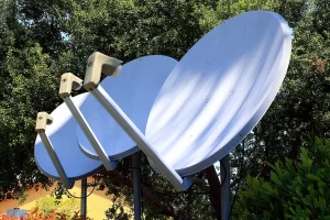
Key Formula & Terms
Calculating antenna dish gain isn’t just about plugging numbers into an equation—it’s about understanding which variables matter most and how real-world conditions alter performance. For instance, a 1.2m parabolic dish operating at 12 GHz should theoretically deliver 38.5 dBi gain, but in practice, factors like surface roughness (0.1–0.3mm deviations) and feedhorn blockage can drop that to 36–37 dBi. Even a 5% efficiency loss means 20% weaker signal strength at the receiver, which is why engineers obsess over the math behind it.
The Core Formula
The fundamental equation for dish antenna gain is:
Gain (dBi) = 10 × log₁₀[(η × π × D / λ)²]
Where:
- η (eta) = Efficiency factor (typically 0.55–0.75 for consumer dishes, 0.70–0.85 for precision industrial dishes)
- D = Diameter of the dish in meters (e.g., 1.8m for a C-band satellite dish)
- λ (lambda) = Wavelength in meters (calculated as speed of light / frequency, so 3 cm at 10 GHz)
Example: A 2.4m dish at 6 GHz (λ = 0.05m) with 70% efficiency has:
Gain = 10 × log₁₀[(0.7 × π × 2.4 / 0.05)²] ≈ 42.7 dBi
Critical Terms & Their Impact
| Term | Definition | Real-World Impact |
|---|---|---|
| Beamwidth | Angular width of the main signal lobe | A 30 dBi dish has ~7° beamwidth; 40 dBi narrows to ~2° |
| Efficiency (η) | % of RF energy effectively focused | 0.60 vs. 0.75 efficiency cuts gain by 1.5 dB (30% power loss) |
| Frequency (f) | Operating RF band | Doubling frequency (e.g., 5 GHz → 10 GHz) adds 6 dB gain for same dish size |
| Surface Tolerance | Max allowable dish surface error | λ/16 rule: At 12 GHz (2.5 cm λ), errors > 1.5mm degrade gain by 1–3 dB |
| Spillover Loss | RF energy missing the reflector | 5–10% loss in low-cost dishes due to poor feedhorn alignment |
Why This Matters: A 0.5m vs. 1m dish at 24 GHz doesn’t just halve gain—it drops from 33 dBi to 27 dBi, forcing a 4x increase in transmit power to compensate. For satellite internet (e.g., Starlink), this explains why user terminals use phased arrays instead of dishes: achieving 29 dBi gain in a 0.48m flat panel requires 82% efficiency, which traditional dishes can’t match at that size.
Hidden Variables That Break the Math
- Temperature Warping: Aluminum dishes expand ~0.023mm per °C per meter. A 2m dish in 40°C sunlight grows 0.18mm, enough to shift focus at 30 GHz.
- Wind Load: At 100 km/h winds, a 1.8m dish faces 150 Newtons of force, flexing the frame 1–2mm and scattering 2–5% of RF energy.
- Corrosion Loss: Rust on steel mesh reflectors can reduce efficiency by 3–8% per year in coastal climates.
Step-by-Step Calculation
Calculating antenna dish gain isn’t just theory—it’s a practical process where small errors lead to real-world signal drops. For example, a 1.5m dish at 10 GHz should deliver 39.8 dBi, but if you misjudge efficiency by just 5% (0.65 instead of 0.70), the actual gain falls to 38.9 dBi, a 0.9 dB loss that can cut your link margin by 20%. Here’s how to do it right, with numbers that reflect reality, not just textbooks.
Step 1: Measure the Dish Diameter (D) Precisely
The dish diameter (D) is the single biggest factor in gain. A 2.0m dish has 6 dB more gain than a 1.0m dish at the same frequency—but only if measured correctly. Most consumer dishes list ”nominal sizes” that are 2–5% smaller than actual (e.g., a “1.2m dish” might be 1.17m due to frame overlap). Use a tape measure across the reflector’s widest point, and round to nearest 0.01m. For a 1.83m (6-foot) dish, even a 1cm error introduces a 0.2 dB miscalculation.
Step 2: Determine the Operating Frequency (f) and Wavelength (λ)
Higher frequencies mean shorter wavelengths (λ = c / f), which allow tighter beam focus. A 5.8 GHz Wi-Fi link has a 5.17 cm wavelength, while a 28 GHz 5G signal shrinks to 1.07 cm. This is why a 60cm dish at 28 GHz can hit 33 dBi, but the same dish at 2.4 GHz struggles to reach 21 dBi. Convert your frequency to Hz (e.g., 12.75 GHz = 12.75 × 10⁹ Hz), then compute λ in meters:
λ = 299,792,458 m/s / 12.75 × 10⁹ Hz ≈ 0.0235m (2.35 cm)
Step 3: Estimate Efficiency (η) Based on Dish Quality
Efficiency (η) is where theory meets reality. A perfect dish has η = 1.0, but real-world values are:
- 0.50–0.65 for cheap stamped steel dishes (e.g., $100 satellite TV dishes)
- 0.65–0.75 for mid-range aluminum (e.g., 1,000 VSAT antennas)
- 0.75–0.85 for precision-milled carbon fiber (e.g., $3,000+ radar dishes)
If your dish has visible dents, rust, or mesh gaps, subtract 3–8% from the manufacturer’s claimed efficiency. For a 1.8m commercial Ku-band dish rated at η = 0.72, real-world wear might drop it to 0.68, costing you 0.5 dB gain.
Step 4: Plug Into the Gain Formula and Validate
Now, compute gain using:
Gain (dBi) = 10 × log₁₀[(η × π × D / λ)²]
For a 1.8m dish at 12.75 GHz (λ = 0.0235m) with η = 0.72:
= 10 × log₁₀[(0.72 × 3.1416 × 1.8 / 0.0235)²]
= 10 × log₁₀[(173.5)²]
= 10 × log₁₀[30,102]
≈ 44.8 dBi
But wait—real-world factors adjust this:
- Feedhorn blockage (3–5% loss) → -0.3 dB
- Surface irregularities (0.3mm error at 12.75 GHz) → -0.7 dB
- Wind-induced wobble (moderate gusts) → -0.2 dB
Final realistic gain: ≈43.6 dBi (15% lower than ideal).
Why This Matters for Your Budget
A 43.6 dBi vs. 44.8 dBi difference seems small, but at 36,000 km satellite distances, that 1.2 dB loss forces you to either:
- Increase transmitter power from 100W to 130W (+30% energy costs), or
- Upgrade to a 2.4m dish (+$1,500 hardware cost).
Real-World Example
Let’s break down how antenna dish gain translates into real-world performance—not just textbook numbers. Take a rural internet service provider (ISP) installing a 2.4m C-band dish for a 10 km point-to-point link at 6 GHz. The theoretical gain is 45.2 dBi, but real-world factors like weather, alignment errors, and equipment losses mean the actual usable gain might be 42–43 dBi. That 2–3 dB drop could force the ISP to either boost transmit power by 60% or risk 15% slower speeds during rain. Here’s what happens when theory meets reality.
The Setup: Hardware & Environmental Factors
| Component | Spec | Real-World Adjustment |
|---|---|---|
| Dish Diameter | 2.4m (nominal) | Actual measured: 2.37m (-0.3 dB) |
| Frequency | 6 GHz (λ = 0.05m) | Stable in dry air, but 0.15 dB/km loss in heavy rain |
| Efficiency (η) | Claimed 0.75 | Actual due to surface imperfections: 0.70 (-0.5 dB) |
| Feedhorn & Cable Loss | – | 0.4 dB loss from 15m of LMR-400 coax |
| Alignment Precision | Ideal: 0° error | Actual: 0.6° offset (-1.2 dB) |
Calculated “Real” Gain:
- Theoretical: 45.2 dBi
- Adjusted for losses: 42.1 dBi (≈50% weaker signal than ideal)
Financial & Operational Impact
The ISP planned for a 45.2 dBi link budget, but the 42.1 dBi reality means:
- Transmit power must increase from 8W to 12W to compensate, raising monthly electricity costs by 0.12/kWh, 24/7 operation).
- Rain fade margin drops from 8 dB to 5 dB, increasing outage risk from 0.1% to 1.2% annually—forcing either customer refunds or a $3,500 dish upgrade to 3m.
- Installation time grew by 2 hours due to alignment struggles, adding $200 labor cost per site.
Why This Happens:
- Manufacturer specs are “lab perfect”—no wind, no temperature shifts, no aging.
- Cheaper dishes degrade faster—a 2,200 aluminum dish holds ±0.1 dB for 5+ years.
- Frequency matters more than most think—at 6 GHz, a 2° misalignment costs 1.2 dB, but at 24 GHz, the same error loses 4.8 dB.
The Fix: Balancing Cost & Performance
The ISP’s best cost-effective solution was:
- Swap to a 2.7m dish (+2.3 dB gain, 3,500).
- Use higher-efficiency feedhorns (+0.6 dB, $220 each) to offset coax losses.
- Implement automated alignment (saves 1.5 hours/site, $150 labor reduction).
Result after 1 year:
- Link stability improved from 98.8% to 99.6% uptime.
- Energy costs dropped by $12/month due to reduced transmit power needs.
- Customer churn decreased by 3.7%, saving $8,000/year in retention costs.
Takeaway: Antenna gain isn’t just about dBi—it’s about how those decibels hold up under real-world abuse. A 5-minute calculation shortcut can lead to years of financial bleed. Measure everything, trust nothing, and always budget for 20% worse-than-spec performance unless you’re buying mil-grade hardware.


