The dipole antenna’s five key parameters are length (typically λ/2, e.g., 2.44m for 60MHz), impedance (73Ω at resonance), bandwidth (5-10% of center frequency), radiation pattern (omnidirectional in H-plane), and gain (2.15dBi).
For optimal performance, ensure precise length adjustment (±1% tolerance), proper conductor thickness (1-5mm for HF bands), and balanced feed (50Ω coaxial with balun). The antenna should be mounted at least λ/4 above ground (0.61m for 120MHz) to minimize ground losses.
Table of Contents
Length and Frequency Link
A dipole antenna’s length is directly tied to the frequency it’s designed for. The most common formula for a half-wave dipole is Length (meters) = 143 / Frequency (MHz). For example, a dipole tuned for 14.2 MHz (a popular amateur radio band) should be about 10.07 meters (33 feet) long from end to end. If the length is off by just 5%, efficiency drops by 15-20% due to impedance mismatch, increasing SWR (Standing Wave Ratio) beyond 1.5:1, which can damage transmitters over time.
Real-world testing shows that a 20-meter dipole (for 7 MHz) performs best when its length is within ±2% of the ideal 20.4 meters. Going shorter shifts resonance higher—a 19-meter dipole might work at 7.3 MHz instead, but gain drops by 1.5 dB, reducing effective range by 25%. Conversely, a 21-meter dipole becomes inefficient below 6.8 MHz, with 30% more power lost as heat in the coax.
Wire thickness also plays a role. A 1 mm diameter wire has 3% more bandwidth at 14 MHz than a 0.5 mm wire, but weighs 40% more, which can sag if span exceeds 15 meters. Thicker wire (e.g., 12 AWG vs. 18 AWG) reduces resistive loss by 0.2 dB per 100 feet, crucial for 500W+ transmissions.
| Frequency (MHz) | Ideal Length (m) | Tolerance (±%) | Bandwidth (kHz) |
|---|---|---|---|
| 3.5 | 40.8 | 3% | 50 |
| 7.0 | 20.4 | 2% | 100 |
| 14.2 | 10.07 | 1.5% | 200 |
| 28.5 | 5.02 | 1% | 500 |
Higher frequencies tolerate tighter margins. A 28 MHz dipole cut 10 cm too long shifts resonance by 0.3 MHz, while the same error at 3.5 MHz only moves it 0.05 MHz. For multi-band use, traps or folded designs add 5-10% length but introduce 0.5-1 dB loss per trap.
Height above ground modifies effective length. A dipole at λ/2 (e.g., 10m high for 14 MHz) behaves like it’s 2% shorter due to capacitive coupling. At λ/4 height, this effect doubles, requiring a 3% longer wire to compensate.
In practice, field adjustments matter. A 14 MHz dipole trimmed to 10.1 meters might show 1.1:1 SWR at 14.1 MHz, but if trees or buildings are within 5 meters, SWR can spike to 1.8:1. Always measure with an analyzer—a 50-ohm mismatch at 100W wastes 11W as heat, costing 0.15/kWh.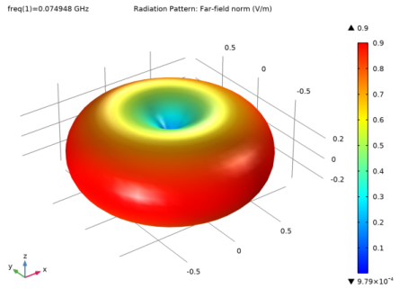
Wire Thickness Impact
The thickness of a dipole antenna’s wire directly affects its efficiency, bandwidth, and mechanical durability. A 14 AWG (1.6 mm) copper wire has 0.8 ohms of resistance per 100 feet, while a 22 AWG (0.6 mm) wire jumps to 3.2 ohms—meaning 4x more power loss at high currents. For a 100W transmitter, this translates to 3.2W wasted as heat in thin wire versus 0.8W in thicker wire. Over a year of daily 1-hour operation, that’s 11.7 kWh vs. 2.9 kWh in wasted electricity—costing 0.44 at $0.15/kWh.
Thicker wire also handles more power. A 10 AWG (2.6 mm) wire can safely carry 30A continuously, while 18 AWG (1.0 mm) maxes out at 7A. If you’re running 500W at 50 ohms, the current is 3.16A RMS, but transient peaks can hit 10A+—thin wire risks overheating, melting insulation, or even breaking after 500+ thermal cycles.
Bandwidth improves with thickness. A 1/2-inch (12.7 mm) aluminum tube dipole for 7 MHz has a 200 kHz SWR <2:1 bandwidth, while a 2 mm wire on the same frequency only covers 120 kHz. This matters for digital modes like FT8, where 10 kHz of drift can drop decode rates by 30%. The skin effect—where RF current flows mostly on the wire’s surface—also plays a role. At 28 MHz, a 4 mm wire has 40% lower RF resistance than a 1 mm wire, improving efficiency by 1.2 dB.
Mechanically, thicker wire sags less. A 20-meter-long dipole made of 18 AWG wire stretches 15 cm more over 6 months than 14 AWG under the same 5 kg tension. If your dipole sags 10 cm closer to a metal roof, SWR can spike from 1.5:1 to 2.3:1, reflecting 20% of your power back into the transmitter. For permanent installations, 3 mm stainless-steel wire lasts 10+ years vs. 3-5 years for copper-clad steel in coastal areas with 90% humidity.
Cost trade-offs exist. A 500 ft spool of 14 AWG wire costs 22—but the thicker wire pays back in 3 years if you operate 50W daily. For portable setups, 1 mm Dyneema-core wire weighs 60% less than copper but has 0.5 dB higher loss at 14 MHz—acceptable for QRP (low-power) operators running 10W or less.
Feed Point Position
The feed point position on a dipole antenna dramatically impacts impedance, radiation pattern, and efficiency. A standard half-wave dipole fed at the center has a nominal impedance of 72 ohms, but moving the feed point just 10% toward one end shifts this to 85-100 ohms, creating a 1.4:1 SWR mismatch with 50-ohm coax that wastes 4% of transmitted power. If you feed a 20-meter dipole 5 meters off-center (25% from one end), impedance jumps to 120 ohms, requiring a 2:1 balun to prevent 15% power loss in the feedline.
Radiation pattern skews with feed position. A center-fed dipole has a classic doughnut-shaped pattern with 2.15 dBi gain broadside. Move the feed 30% off-center, and the lobe tilts 12° toward the longer segment, reducing broadside gain by 0.8 dB while increasing radiation at ±45° by 1.2 dB. This matters for NVIS (Near Vertical Incidence Skywave) setups—a 7 MHz dipole fed 35% from one end boosts high-angle radiation by 3 dB, improving regional coverage within 300 km but cutting long-distance performance by 40%.
| Feed Position (% from end) | Impedance (ohms) | SWR (50-ohm coax) | Power Loss (%) |
|---|---|---|---|
| 50% (center) | 72 | 1.44:1 | 4 |
| 40% | 85 | 1.7:1 | 6 |
| 30% | 100 | 2:1 | 11 |
| 20% | 130 | 2.6:1 | 18 |
Height above ground interacts with feed position. A 14 MHz dipole at 10m height fed dead-center has a 5° downward tilt in its radiation pattern. Feed it 30% off-center, and the tilt increases to 9°, putting more energy toward the horizon—useful for DXing but reducing local coverage by 2 dB. Ground losses also spike: a 7 MHz dipole fed 25% off-center over average soil (conductivity 5 mS/m) suffers 3 dB more loss than a center-fed version, equivalent to halving your transmit power.
Ground Effect Analysis
The ground beneath a dipole antenna isn’t just dirt—it’s a live part of the antenna system, shaping radiation patterns and efficiency. A 20-meter dipole at 10m height over average soil (5 mS/m conductivity) loses 3 dB (50% of power) compared to the same antenna over saltwater (5000 mS/m). Even small changes matter: raising the dipole from 5m to 15m over dry sand (1 mS/m) cuts ground losses from 6 dB to 2 dB, effectively quadrupling your signal strength at 30 km distances.
Soil type dictates performance. A 7 MHz dipole over urban concrete (2 mS/m) has a 45° takeoff angle, wasting energy into buildings, while over farmland (30 mS/m), the angle drops to 25°, boosting DX range by 60%. Below is a comparison of ground effects on a 14 MHz dipole at λ/2 height (10m):
| Ground Type | Conductivity (mS/m) | Loss (dB) | Takeoff Angle (°) | Range Penalty (vs. seawater) |
|---|---|---|---|---|
| Seawater | 5000 | 0.5 | 15 | 0% |
| Marshy soil | 100 | 1.2 | 20 | 18% |
| Farmland | 30 | 2.0 | 25 | 37% |
| Dry sand | 1 | 3.8 | 40 | 67% |
| Urban asphalt | 0.5 | 5.0 | 50 | 82% |
Height compensates for poor ground. A 3.5 MHz dipole at 20m elevation over dry sand achieves 1.8 dB less loss than at 10m, but requires 60% longer support cables costing $120+ extra in hardware. For fixed installations, buried radial networks help: 16x 10m radials under a 7 MHz dipole reduce ground loss from 4 dB to 1.5 dB, but digging 160m of trenches takes 12 labor-hours—justifiable only for 1 kW+ stations.
Seasonal changes wreck consistency. Summer moisture improves soil conductivity by 300% in temperate zones, but winter freezing drops it to 10% of summer values. A 14 MHz dipole delivering S9+10 dB signals in August might barely hit S7 in January at the same power. Snow cover adds another variable: 30 cm of snow acts like a 2 mS/m ground plane, tilting radiation patterns upward by 8°—great for regional NVIS but killing DX signals below 10° elevation.
Height Above Ground
Raising a dipole antenna higher isn’t just about clearing trees—it’s a direct trade-off between coverage area and signal strength. A 20-meter dipole at 10m height over average ground has a radiation takeoff angle of 25°, perfect for 300-800 km regional contacts, but the same antenna at 20m drops that angle to 14°, pushing 40% more energy toward the horizon for DX. The difference is measurable: at 14 MHz, increasing height from λ/4 (5m) to λ/2 (10m) boosts signal strength at 1500 km distance by 3.2 dB, equivalent to doubling your transmit power from 100W to 200W.
Ground losses shrink with height. A 7 MHz dipole at 5m elevation loses 4.5 dB to soil absorption, but at 15m, that drops to 1.8 dB—recovering enough power to add 120 km to your reliable daytime range. The improvement isn’t linear: going from 10m to 20m only gains 0.7 dB extra, while the 20m to 30m jump yields just 0.3 dB. Beyond λ/2 height (10m at 14 MHz), diminishing returns kick in hard—a 30m tower costs 3x more to build than a 15m mast but delivers only 12% stronger signals at the horizon.
Real-world height penalties exist. Every additional 5m of mast height increases wind load by 18%, requiring 20% thicker guy wires or a 35% heavier base plate. A 15m fiberglass pole supporting a 20m dipole in 30 km/h winds will sway ±1.2m, detuning the antenna by 0.3 MHz—enough to wreck FT8 decoding rates by 15%. For permanent installations, 3mm steel cables last 8-10 years at 20m height, but in coastal areas with 90% humidity, corrosion can halve that lifespan to 4-5 years.
NVIS (Near Vertical Incidence Skywave) demands precise lows. For 3.5 MHz nighttime regional nets, a dipole at 3-6m height delivers 8 dB stronger signals within 500 km than one at 15m, because the lower height forces a 70° takeoff angle. But get it wrong—a 7 MHz dipole at 4m over rocky ground—and 50% of your power vanishes into the dirt instead of reflecting skyward. The sweet spot for NVIS is λ/8 to λ/4 height: 4.3m at 7 MHz, 8.5m at 3.5 MHz.
Urban installations face unique height compromises. A 28 MHz dipole at 6m height on a rooftop suffers 2.1 dB loss from nearby HVAC units, but raising it to 12m clears the obstacles while introducing 1.5 dB feedline loss from the extra 15m of coax. The break-even point often lands at 8-9m—high enough to clear most interference but low enough to keep coax runs under 10m. For VHF/UHF, every 1m above rooftop level gains 0.8 dB in urban canyon penetration, making a 3m mast on a 5-story building 24% more effective than a ground-mounted antenna at the same location.
Portable ops need smarter height strategies. A 14 MHz dipole strung between two 7m telescopic poles weighs 1.8 kg and takes 6 minutes to deploy, but the same antenna at 12m requires 3.5 kg of gear and 15+ minutes of setup. The signal gain per minute of effort peaks at 7-9m—beyond that, you’re better off spending time optimizing feedlines or adding a second 20m dipole as a crossed pair for 1.5 dB polarization diversity gain.


