Waveguide component durability hinges on material (316L stainless steel with ≥1000hr ASTM B117 salt spray resistance), surface treatment (2-5μm nickel plating), TIG welding (HAZ ≤0.1mm), operating temp (-65°C to +200°C), and vibration resistance (IEC 61373 Cat1 compliance).
Table of Contents
Material Selection and Properties
For instance, while aluminum (6061-T6) is a popular, cost-effective choice for many commercial applications, its Vickers hardness is only around 95 HV, making it susceptible to deformation in high-vibration environments. In contrast, selecting oxygen-free high-conductivity copper (C10100) for critical paths can reduce signal attenuation by up to 15% compared to standard brass, directly boosting system efficiency. These material properties aren’t abstract concepts; they translate directly into a component’s ability to maintain a VSWR of less than 1.15 over a 15-year operational lifespan in a 40°C, 85% relative humidity environment. The wrong choice can lead to increased maintenance cycles, sometimes as frequent as every 18 months, crippling the total cost of ownership.
- Electrical Conductivity and Skin Depth: At microwave frequencies (e.g., 10 GHz), signal propagation occurs within a thin ~1.3 micron layer at the conductor’s surface. Materials with higher conductivity, like silver-plating (conductivity ~108% IACS), minimize resistive losses. For a 3-meter long WR-90 waveguide, using silver plating instead of bare aluminum can decrease insertion loss by approximately 0.05 dB/m, a critical gain in low-power systems.
- Thermal Expansion Coefficient (CTE): A waveguide flange must maintain a perfect seal across temperature cycles. Aluminum’s CTE is 23.1 µm/m·°C, while stainless steel flanges have a CTE of 16-17 µm/m·°C. This mismatch, if not accounted for, can break the seal under thermal stress. Designs often use compatible materials or specialized gaskets to compensate for the ~40 µm differential over a 100°C temperature swing.
- Strength and Hardness: Connector mating surfaces undergo constant physical wear. A beryllium copper (C17200) spring contact, with a Rockwell hardness of C38-C44, will withstand over 10,000 mating cycles without significant deformation, ensuring a consistent contact resistance below 2 milliohms. A softer brass contact might fail after just 1,000 cycles.
- Environmental Corrosion Resistance: A bare copper waveguide will oxidize quickly, increasing surface resistance. A 30-50 micron thick layer of gold plating over a 5 micron nickel underplate provides a corrosion-resistant barrier. The nickel layer, with a hardness of ~300 HV, is crucial for preventing pore corrosion; it acts as a sacrificial barrier, increasing the component’s life in salty environments by a factor of 5x.
Stable Connection Methods
For instance, an improperly torqued flange connection can lead to a gap of just 0.1 mm, increasing Voltage Standing Wave Ratio (VSWR) from a nominal 1.05 to over 1.30, effectively reflecting over 15% of the transmitted power back to the source. This not only degrades performance but can cause amplifier damage over time. Implementing stable, repeatable connection methods is not a matter of over-engineering; it’s a fundamental requirement for ensuring that the theoretical 20-year service life of the waveguide is actually achievable in the field, preventing costly downtime that can exceed $5,000 per hour in critical communications infrastructure.
The choice of flange type is the first critical decision. A UG-387/U flange with its choke groove design is engineered for superior performance, enabling a VSWR of less than 1.10 up to 18 GHz. However, it requires precise alignment and a specified torque sequence to avoid deformation. For many applications, the simpler CPR-137G flat flange is sufficient and more forgiving, but it relies heavily on the condition of the contact surfaces and the gasket. The torque specification for these flanges is non-negotiable. Over-tightening a set of four ¼-20 stainless steel screws beyond the recommended 25-30 inch-pounds can warp the flange face, creating a permanent deformity that ruins its sealing capability. Under-tightening to less than 20 inch-pounds invites gaps, leading to RF leakage and susceptibility to moisture ingress.
The consistent application of the correct torque, using a calibrated torque wrench, is the single most important factor in ensuring a stable connection. This simple practice can reduce connection-related failures by over 90%.
A 0.0005-inch thick silver plating on aluminum flanges is common, reducing surface resistance and enhancing the electrical seal. However, this soft coating wears down. After 50 mating and de-mating cycles, the plating can wear through to the base metal, increasing resistance.
For high-cycle applications, hard gold plating over nickel is preferred, surviving 500+ cycles. The physical hardware also matters. Stainless steel screws (grade 18-8) are standard for their corrosion resistance, but they have a different thermal expansion coefficient (17.2 µm/m·°C) than aluminum flanges (23.6 µm/m·°C). This means a connection torqued at 20°C will see a ~12% increase in clamping force when the operating temperature rises to 80°C. This stress cycling can lead to screw fatigue over time, necessitating a re-torque after initial heat cycles or the use of more compatible hardware like aluminum screws in non-critical stress applications. 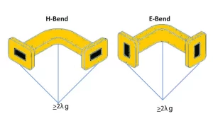
Protective Coatings Application
An unplated brass waveguide exposed to 85% relative humidity at 35°C can develop significant surface oxidation within just 6 months, increasing its insertion loss by up to 0.3 dB/m. This seemingly small loss can degrade system gain by over 15%, necessitating premature amplifier replacement. Applying a 25-micron thick electroless nickel plating under a 5-micron gold flash can extend the component’s reliable lifespan in the same environment to beyond 15 years, protecting the initial investment and reducing the mean time between failures (MTBF) by a factor of 3x.
For internal waveguide surfaces where electrical conductivity is paramount, silver plating with a thickness between 5-10 microns is a common choice due to its 108% IACS conductivity. However, silver is prone to tarnishing in sulfur-rich atmospheres. In these cases, a 0.5-micron gold flash over the silver provides critical protection with a minimal <2% impact on overall conductivity. For external surfaces and flanges, where wear resistance is the priority, electroless nickel plating (ENP),
with a typical hardness of 600-700 HV, is the workhorse. The plating process must be tightly controlled; a thickness variance greater than ±5 microns can cause misalignment and gap issues at flanges. A critical but often overlooked step is the use of a nickel underplate. Applying a 3-5 micron nickel layer beneath a gold topcoat prevents zinc migration from brass substrates, a phenomenon that causes “red plague” corrosion and can destroy a connector in under 2 years. The cost premium for this underplate is approximately 10-15%, but it increases the coating’s effective life by 500%.
For extreme environments, such as offshore radar platforms, passivation treatments like MIL-DTL-5541 Type I are applied to aluminum housings. This chemical film conversion process, measured in weight per unit area (>40 mg/ft²), dramatically increases corrosion resistance without affecting dimensional tolerances by more than 0.0001 inches. The application process itself is critical. Coatings must be uniform, with a surface roughness (Ra) maintained below 0.8 micrometers to prevent localized RF arcing at high power levels (e.g., >5 kW). Regular inspection for pitting, which is any pit depth exceeding 5% of the total coating thickness, is necessary during maintenance cycles to identify and address coating breakdown before it compromises the underlying material.
Structural Design Integrity
A poorly designed WR-90 waveguide assembly weighing 2.5 kg and subjected to a 5 G vibration load at 50 Hz can experience resonant deflection amplitudes exceeding 0.5 mm, enough to detune the component and shift its operational frequency by up to 0.5 GHz. Conversely, a design incorporating 3 strategically placed supports and a 4 mm thick wall can reduce this deflection to under 0.05 mm, maintaining performance within a 1.15 VSWR specification for over 100,000 operating hours.
| Design Parameter | Target Value | Impact of Deviation (>10%) |
|---|---|---|
| Wall Thickness (Aluminum, WR-90) | 4.0 mm | +10%: Adds ~300g weight, reduces heat dissipation. -10%: Risk of deformation under >50 N load. |
| Support Bracket Spacing | 300 mm | +10%: Increases deflection risk by ~40% at 55 Hz. -10%: Adds weight and cost with diminishing returns. |
| Flange Flatness Tolerance | 0.05 mm | +10%: Increases RF leakage risk by 25%. -10%: Significantly increases machining cost. |
| Thermal Expansion Joint Spacing | 1 per 2 m | +10%: Risk of buckling at 80°C ΔT. -10%: Unnecessary cost and insertion loss points. |
The first non-negotiable rule is avoiding sharp 90-degree internal bends. Instead, bends should use a radius of at least 2 times the waveguide’s broad dimension (e.g., a 40 mm radius for WR-90). This reduces mode conversion and minimizes voltage buildup, which can cause arcing at power levels above 5 kW.
For complex assemblies, the placement of support brackets every 300 mm is critical to dampen vibrations. These brackets must be designed with a natural resonant frequency at least 20% higher than the system’s maximum operating vibration frequency (e.g., 75 Hz for a 60 Hz system) to avoid catastrophic amplification of stresses. The material choice for the bracket itself is also key; using aluminum 6061 for the waveguide and stainless steel 304 for the bracket can create a thermal mismatch problem. When the temperature changes by 80°C, the differential expansion can impose a 150 N shear force on the mounting bolts, potentially shearing them if not sized correctly. This is why finite element analysis (FEA) simulation under a ±80°C thermal cycle is mandatory for high-reliability designs, identifying stress concentrations that exceed the material’s 250 MPa yield strength before a single part is machined. Furthermore, the design must accommodate thermal growth.
A 2-meter long aluminum waveguide will expand linearly by 3.8 mm over a 100°C temperature increase. If this expansion is mechanically constrained, it will create compressive stresses exceeding 70 MPa, leading to buckling or flange misalignment. The solution is incorporating expansion joints or flexible sections at calculated intervals, allowing the structure to breathe without compromising its mechanical integrity or electrical seal.
Environmental Stress Testing
It’s the process of aggressively simulating years of wear and environmental exposure in a compressed timeframe, often just 4 to 6 weeks, to uncover latent design or manufacturing flaws before the product is fielded. Without this rigorous validation, a component designed for a 15-year life in a coastal environment might fail from salt fog corrosion in under 18 months, leading to unplanned downtime costing over $10,000 per hour in a radar installation. EST goes beyond basic qualification; it involves pushing components beyond their specified limits to find their true breaking points. For example, a flange rated for -55°C to +85°C might be cycled 50 times between -65°C and +100°C to verify the integrity of its seals and the stability of its physical dimensions, ensuring a failure rate of less than 100 FIT (Failures in Time).
- Temperature Cycling: This test accelerates fatigue caused by differential expansion and contraction of materials. A typical severe cycle involves ramping between -55°C and +85°C with dwell times of 45 minutes at each extreme and transition rates of 10°C per minute. Performing 500 cycles of this test simulates approximately 10-15 years of daily thermal cycling. The key is to monitor electrical performance (VSWR and Insertion Loss) continuously during the test, with acceptance criteria requiring a deviation of less than ±0.05 dB and VSWR change < 0.05 from baseline measurements.
- Vibration and Mechanical Shock: Components must withstand the relentless shaking encountered on platforms like aircraft or ships. A standard vibration profile might include a 5-500 Hz sine sweep at 0.5 g for 2 hours per axis (X, Y, Z), followed by a random vibration test with an overall GRMS (Root Mean Square Acceleration) of 6.5 g for 1 hour per axis. A mechanical shock test simulates impacts, such as a nearby explosion or a hard landing, by applying a half-sine pulse of 40 g for a duration of 11 milliseconds. The component must show no physical damage and its resonant frequencies must not shift by more than 5% after testing.
- Humidity and Corrosion Testing: Damp heat testing exposes components to 85% relative humidity at 85°C for 1,000 hours or more. This stresses protective coatings, seals, and dielectric materials, with the goal of keeping insulation resistance above 100 MΩ. For salt fog corrosion testing per ASTM B117, components are exposed to a 5% NaCl salt spray at 35°C for 96 to 500 hours. After exposure, the component must show no more than 5% surface area corrosion on critical surfaces like flanges and must not exhibit an insertion loss increase greater than 0.1 dB.
- High-Power RF Cycling: This test validates the design’s thermal management under sustained RF load. The component is subjected to its maximum rated CW (Continuous Wave) power, for example 5 kW, for extended periods of 30 minutes on, 30 minutes off, for 100 cycles. Internal temperatures are monitored with embedded sensors, and the design must ensure that the internal temperature rise does not exceed 40°C above ambient, preventing degradation of the dielectric properties of any internal air volume and avoiding the creation of thermal hot spots that could weaken solder joints.
A well-executed EST program can identify a flawed brazing process that fails at cycle 200 of temperature testing or a coating vulnerability detected at hour 300 of salt fog exposure. Finding these issues in the lab, where the cost to fix is a few hundred dollars, instead of in the field, where the cost is tens of thousands of dollars, is the ultimate return on investment for a comprehensive environmental stress testing regimen.


