The three main open-ended waveguide types are rectangular (e.g., WR-90 with 22.86mm×10.16mm dimensions for 8-12GHz), circular (30mm diameter supporting TE11 mode at 3GHz), and sectoral (60° angle for directional coupling, optimized for 10-15GHz testing).
Table of Contents
Standard Rectangular Waveguide Design
Their design is standardized by a numbering system (like WR-90), where the “WR” prefix stands for “Waveguide, Rectangular.” The internal dimensions are precisely machined, typically from aluminum or brass, with a common standard like WR-90 having an interior width of 2.286 cm (0.9 in) and a height of 1.016 cm (0.4 in). These exact dimensions are not arbitrary; they directly determine the waveguide’s operating frequency band. For WR-90, the recommended operating frequency range is from 8.2 GHz to 12.4 GHz, a band known as X-band. This design efficiently handles high power levels, often exceeding several hundred kilowatts in pulsed radar applications, with very low transmission loss, typically less than 0.1 dB per meter within its passband.
- Cut-off Frequency: The absolute lowest frequency the waveguide can support.
- Dominant Mode: The basic, most efficient pattern of wave propagation (TE10 for rectangular).
- Impedance Matching: Minimizing signal reflections at the open-ended aperture.
The operational principle hinges on its cut-off frequency, which is approximately 6.56 GHz for the WR-90 waveguide. This is the absolute lowest frequency at which signals can propagate. Below this frequency, waves are attenuated exponentially and cannot travel through the guide. The dominant mode of operation is the Transverse Electric (TE10) mode, where the electric field is perpendicular to the direction of propagation and varies in strength across the wide dimension of the guide. The phase velocity of a wave inside an air-filled waveguide is greater than the speed of light, which is a result of the guiding effect of the metallic walls and does not violate special relativity.
The wave impedance inside the guide does not match the 377-ohm impedance of free space, leading to a significant portion of the energy being reflected back towards the source. This results in a high Voltage Standing Wave Ratio (VSWR), often worse than 5:1 or even 10:1 over a broad frequency range, making it a very inefficient radiator by itself.
A well-designed flange can reduce the VSWR to below 2:1 over a 10-15% bandwidth, dramatically increasing radiative efficiency. The size of the flange is a key design parameter, with a typical diameter of one to two wavelengths at the operating frequency to effectively suppress backlobes. The primary application for these radiators is in close-range sensing and illumination, where broad coverage is acceptable, such as in industrial radar level gauges or proximity sensors. Their simple, rugged construction allows them to operate in harsh environments with temperatures ranging from -40°C to +85°C and high humidity, making them a cost-effective solution for many commercial and industrial systems.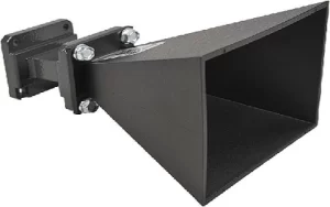
Circular Waveguide with Symmetry
Standard sizes, such as the WC-98, have a precise internal diameter of 2.489 cm (0.98 in), which sets its dominant mode cut-off frequency at approximately 6.26 GHz. This symmetry supports a key feature: polarization diversity. The dominant mode, Transverse Electric 11 (TE11), is degenerate, meaning waves with horizontal, vertical, or any rotational polarization can propagate with identical characteristics. This makes them indispensable in systems where polarization must be controlled or changed, such as in satellite communications links operating in the 7.25 to 7.75 GHz downlink band, where a circular waveguide is often the feed element for an antenna.
- Polarization Stability: Maintaining the intended polarization plane of the transmitted wave.
- Low Attenuation: Exhibiting lower transmission loss per unit length compared to rectangular guides.
- Mode Purity: The challenge of suppressing higher-order modes (like TM01) to ensure a clean radiation pattern.
The most significant feature of a circular waveguide is its ability to handle dual-polarization signals simultaneously without any difference in phase velocity. This is critical for modern satellite communications payloads that employ polarization division multiplexing, effectively doubling the data capacity within the same 500 MHz wide frequency channel. However, this symmetry introduces a major design challenge: mode conversion and stability. The desired TE11 mode can easily degenerate into other unwanted modes, like the TM01 mode, at imperfections or bends, distorting the radiation pattern. The attenuation constant for the TE11 mode in a copper WC-98 guide is exceptionally low, around 0.02 dB per meter at 10 GHz, which is roughly 20-30% lower than a comparable rectangular guide, making it more efficient for long waveguide runs in large antenna systems.
An unmatched open-ended circular waveguide suffers from similar high VSWR issues as a rectangular one, often exceeding 8:1. The radiation pattern is omni-directional in the H-plane but has a narrower beamwidth in the E-plane. The 3-dB beamwidth in the E-plane is typically around 75 degrees, while the H-plane beamwidth is closer to 90 degrees for a bare aperture. To make it a practical radiator, two key modifications are almost always employed:
- A Flared Section (Conical Horn): This is the most common solution. Flaring the end into a horn dramatically improves impedance matching to free space, reducing VSWR to below 1.5:1 over a 10-15% bandwidth, and provides significant gain, typically between 10 to 15 dBi for a moderately sized horn.
- A Dielectric Plug: A carefully sized dielectric constant material (e.g., PTFE with εr ≈ 2.1) can be inserted into the aperture. This plug acts as an impedance transformer, matching the ~500-ohm wave impedance inside the guide to the 377-ohm free space impedance, boosting radiative efficiency.
The primary application of open-ended circular waveguides is as feeds for parabolic reflector antennas in C, X, and Ku bands (4-18 GHz). Their symmetry ensures identical performance regardless of the antenna’s rotational angle relative to the feed, which is crucial for tracking antennas. They are also the fundamental building block for corrugated horns, which use rings of grooves to create a hybrid HE11 mode, resulting in an exceptionally symmetric radiation pattern with very low side-lobes (< -25 dB) and minimal cross-polarization (< -30 dB), which is a requirement for satellite downlink reception and radio astronomy telescopes like the VLBA.
Flared Sectoral Waveguide Applications
A common E-plane sectoral horn, derived from a standard WR-430 waveguide (height: 4.318 cm, width: 10.922 cm) for 2.3-3.3 GHz S-band operations, might have a flare angle of 25 degrees and a flare length of 60 cm. This controlled expansion in one dimension transforms the guided wave into a directed beam, providing a gain of approximately 15 dBi and reducing the typical unmatched VSWR from over 10:1 to below 1.3:1 across its 20% operational bandwidth.
For a horn with an aperture of 25 cm in the E-plane, the beamwidth will be roughly 20 degrees at 3 GHz. Conversely, the H-plane beamwidth remains largely unchanged from the original waveguide’s dimension, resulting in a fan-shaped or sectoral pattern. This asymmetric beam is highly desirable for point-to-multipoint radio links and cellular base station sector antennas, where coverage of a specific angular slice, like a 120-degree sector, is required. The side-lobe levels are typically maintained below -12 dB to minimize interference between adjacent sectors. The gain improvement is directly calculable from the aperture size; an E-plane flare that doubles the aperture dimension in that plane can yield a ~3 dB increase in gain due to the larger radiating area.
The key advantage of a sectoral horn over a simple open-ended waveguide is its controlled, predictable pattern and vastly improved impedance match, which directly translates to higher radiated efficiency and system gain.
The phase error across the aperture must be kept below 90 degrees to avoid significant pattern degradation, which places a practical limit on the allowable flare angle for a given desired gain. These horns are rarely used in isolation at microwave frequencies due to their asymmetric pattern. Instead, they are employed as feed elements for offset parabolic reflector antennas in satellite communications, where they illuminate the dish to achieve a high gain, symmetrical pattern. Their most cost-sensitive application is in motion sensors and radar detectors at 10.525 GHz or 24.125 GHz, where a small, inexpensive printed circuit board (PCB)-etched horn provides just enough directivity to cover a hallway or driveway with a range of 15-20 meters.


