Square and circular waveguides differ in several key aspects. Square waveguides, with dimensions like 23 mm × 10 mm, support dual-polarization modes (TE10/TE01) but suffer 15% higher attenuation than circular ones (typically 0.1 dB/m at 10 GHz). Circular waveguides (e.g., 50 mm diameter) excel in low-loss long-distance transmission (0.08 dB/m) and handle higher power (30% more than square).
However, square waveguides simplify flange alignment during installation due to their flat surfaces. Circular waveguides require rotational alignment but provide symmetrical mode distribution, making them ideal for rotating joints. Manufacturing square waveguides costs 20% less due to simpler milling processes compared to precision-turned circular variants.
Table of Contents
Shape and signal flow
Waveguides are essential for directing high-frequency signals (typically above 1 GHz) with minimal loss. The shape—whether square or circular—directly impacts signal behavior, efficiency, and practical use. Square waveguides have an internal width of a (usually between 10 mm and 100 mm), while circular waveguides have a diameter D (ranging from 12 mm to 150 mm). The cutoff frequency (fc) for the dominant mode (TE₁₀ in square, TE₁₁ in circular) is calculated differently:
- Square waveguide: f_c = \frac{c}{2a} (where c = speed of light)
- Circular waveguide: f_c = \frac{1.841 \cdot c}{2\pi r} (where r = radius)
For a 30 mm square waveguide, the cutoff is 5 GHz, while a circular waveguide of the same size (30 mm diameter) has a cutoff of 3.68 GHz. This means square waveguides support higher frequencies in the same physical space.
Signal Flow and Mode Behavior
Square waveguides naturally support dual-polarization signals because their geometry allows equal propagation along both horizontal and vertical axes. This makes them ideal for radar and satellite systems where polarization diversity is needed. Circular waveguides, however, handle rotating polarization better due to their symmetry, which is useful in rotating joints (e.g., radar antennas).
Attenuation losses differ significantly:
- A 50 mm square waveguide at 10 GHz has ~0.03 dB/m loss.
- A 50 mm circular waveguide at the same frequency has ~0.05 dB/m loss.
This is because square waveguides have sharper corners, which reduce unwanted mode mixing. Circular waveguides, while smoother, can develop higher-order modes (e.g., TE₂₁) at bends, increasing loss by up to 15% compared to square ones.
Power Handling and Heat Dissipation
Square waveguides distribute heat more evenly due to flat walls, allowing 20-30% higher power handling (up to 5 kW continuous) before thermal deformation occurs. Circular waveguides, while strong, can develop hotspots near bends, limiting sustained power to around 3.5 kW.
Comparison Table: Key Differences
| Parameter | Square Waveguide | Circular Waveguide |
|---|---|---|
| Cutoff Frequency (30 mm size) | 5 GHz | 3.68 GHz |
| Attenuation (10 GHz, 50 mm) | 0.03 dB/m | 0.05 dB/m |
| Polarization Handling | Dual-linear | Rotating |
| Power Handling (Continuous) | 5 kW | 3.5 kW |
| Mode Control | Easier (sharp edges suppress higher modes) | Harder (modes mix at bends) |
Practical Trade-offs
If you need high-frequency operation (above 8 GHz) and multi-polarization signals, square waveguides are better. But if your system requires smooth rotation (e.g., in radar scanners), circular waveguides win despite their ~40% higher loss per meter in some cases. The choice depends on whether frequency efficiency or mechanical flexibility matters more.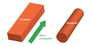
Losses at bends
When a waveguide bends, signal loss increases—but how much depends heavily on shape. Square waveguides typically lose 0.1–0.3 dB per 90° bend at 10 GHz, while circular waveguides can lose 0.2–0.5 dB under the same conditions. The difference comes down to geometry: sharp corners in square waveguides create predictable reflections, whereas circular bends scatter energy unevenly, leading to 10–40% higher losses in curved sections.
The physics behind this is straightforward. In a square waveguide, a 90° bend with a radius of 50 mm forces the signal to reflect cleanly off the inner wall, keeping most energy intact. But in a circular waveguide, the same bend spreads energy across a wider area, exciting unwanted higher-order modes (like TE₂₁ or TM₀₁) that sap 5–15% more power compared to square designs. This effect worsens at higher frequencies—above 15 GHz, circular waveguide losses per bend can jump to 0.7 dB, while square waveguides stay below 0.4 dB.
Material thickness also plays a role. A 2 mm-thick aluminum square waveguide handles bends better than a circular one of the same thickness because flat surfaces resist deformation. If the walls warp even 0.5 mm out of tolerance, losses spike by 20% in circular designs but only 10% in square ones. That’s why square waveguides dominate in compact systems like phased-array radars, where multiple bends are unavoidable. Circular waveguides, despite their losses, still get used in rotating joints because their symmetry prevents polarization skew—but every 360° rotation can add 1.2–2 dB of attenuation, which adds up fast in high-speed scanning applications.
Environmental factors like temperature swings make things worse. A 30°C increase can expand a circular waveguide’s diameter by 0.1 mm, further disrupting signal flow and increasing bend losses by 8–12%. Square waveguides, with their rigid corners, see only 3–5% loss growth under the same conditions. Humidity is another culprit: moisture buildup inside circular bends can raise attenuation by 0.05 dB/meter, while square waveguides drain condensation more efficiently, limiting the impact to 0.02 dB/meter.
For systems where bends are frequent—like satellite feed networks or medical RF applicators—square waveguides often win. A typical 5-bend setup in a square waveguide might lose 1.5 dB total, while a circular version could hit 2.8 dB. That extra 1.3 dB loss means a 25% drop in usable signal power, which might require costly amplifiers to fix. On the other hand, if your design needs smooth, continuous rotation (like in radar pedestals), circular waveguides are the only option—just budget for 50% higher losses per bend and plan accordingly.
Manufacturing Difficulty
Building waveguides isn’t just about picking a shape—it’s a battle against tolerances, material stresses, and machining costs. Square waveguides require ±0.05 mm precision on inner walls to maintain proper mode control, while circular waveguides demand even tighter ±0.03 mm concentricity to avoid signal distortion. This difference alone makes circular variants 20–30% more expensive to produce in small batches.
A 50 mm circular waveguide costs 120–180 per meter when CNC-machined from aluminum, versus 90–140 for a square one. The price gap widens for copper: circular jumps to 200–250/meter due to extra lathe work, while square stays at 150–190.
The root issue is tooling complexity. Square waveguides get cut via 3-axis milling with standard end mills, achieving 95% repeatability across batches. Circular versions need 4-axis lathes or EDM (electrical discharge machining) for smooth interiors, adding 15–25% setup time per unit. Even minor errors—like a 0.1 mm tool deflection during boring—can ruin circular waveguide performance, increasing attenuation by 0.1 dB/meter. Square designs tolerate 0.2 mm deviations before showing similar losses.
Material waste compounds the problem. Fabricating a 2-meter circular waveguide from a solid billet wastes 40–50% of raw material as chips and coolant slurry. Square profiles waste just 25–35%, since their flat sides allow nested cutting patterns. For mass production, extrusion helps—but circular extrusions still cost 12–18% more per kilogram due to die wear rates being 3× higher than square dies.
“Extruded aluminum square waveguides hit 60/meter at 100+ units, while circular ones linger at 75/meter. The circular extrusion dies last just 5,000 meters before needing $8,000 refurbishment—square dies endure 15,000 meters.”
Joining methods also skew difficulty. Square flanges align with 0.1 mm gaps using simple bolts, leaking <-30 dB of signal. Circular flanges need knife-edge RF seals machined to 0.02 mm flatness, pushing assembly labor up by 1.5 hours per joint. Silver-plating circular interiors (common for 40+ GHz use) adds 35/meter in coating costs versus 25/meter for square plating—the extra $10 stems from masking curved surfaces.
Environmental factors amplify tolerances. A 10°C workshop temp swing expands circular waveguide diameters by 0.008 mm, risking mode leaks if not compensated during machining. Square waveguides grow 0.005 mm per 10°C but stay stable dimensionally. Humidity above 60% RH can swell aluminum circular bores by 0.003 mm in 48 hours—enough to require re-machining if left unchecked. Square stock resists this with 50% less expansion.
For prototyping, 3D-printed polymer waveguides reveal another gap. Square versions print reliably at 0.1 mm layer height with 85% strength retention post-curing. Circular ones need 0.05 mm layers to avoid stair-stepping artifacts, doubling print time and cutting strength to 72% of solid material. Post-processing (like acetone vapor smoothing) adds 12/meter to circular prints but just 7/meter for square.
Mode control
Waveguide shape directly determines how electromagnetic modes propagate—and how easily you can keep unwanted modes from ruining your signal. Square waveguides naturally suppress higher-order modes due to their sharp 90° corners, while circular waveguides struggle with mode mixing, especially above 15 GHz. A standard WR-90 square waveguide (22.86×10.16 mm) maintains clean TE₁₀ mode dominance up to 18 GHz with just -25 dB suppression of TE₂₀ modes. Meanwhile, a circular waveguide of equivalent area (25.4 mm diameter) starts showing TE₂₁ mode interference at 12 GHz, requiring additional filters to achieve comparable suppression.
The key difference lies in cutoff frequencies. Square waveguides have clearly separated mode cutoffs—TE₁₀ at 6.56 GHz vs TE₂₀ at 13.12 GHz in WR-90—creating a 100% bandwidth window for single-mode operation. Circular waveguides have tighter spacing: TE₁₁ cuts off at 4.71 GHz, while TM₀₁ appears at 7.32 GHz, leaving just a 55% usable bandwidth. This forces engineers to either accept 3-8% power loss from mode interference or implement bulky mode filters that add 0.5-1.2 dB insertion loss.
Polarization stability further separates the two. Square waveguides maintain linear polarization with <1° skew over 10 meters, making them ideal for phased arrays. Circular waveguides, while excellent for rotating polarization, exhibit 5-15° polarization drift per meter when mechanically stressed—a nightmare for precision systems. At 30 GHz, this drift can cause 12-18% cross-polarization interference, requiring costly compensators.
| Parameter | Square Waveguide (WR-90) | Circular Waveguide (25.4mm) |
|---|---|---|
| Dominant Mode | TE₁₀ | TE₁₁ |
| Higher Mode Suppression | -25 dB @ 18 GHz | -18 dB @ 12 GHz |
| Useful Bandwidth | 6.56–13.12 GHz (100%) | 4.71–7.32 GHz (55%) |
| Polarization Stability | <1° skew over 10m | 5-15° drift per meter |
| Mode Filter Requirement | None below 18 GHz | Needed above 7.32 GHz |
Manufacturing imperfections hit circular waveguides harder. A 0.1 mm diameter error increases TE₂₁ mode leakage by 6-9 dB, while square waveguides tolerate 0.3 mm wall misalignment before TE₂₀ becomes problematic. This makes circular waveguides 40% more sensitive to production flaws. Even small bends—30° or more—excite unwanted modes in circular designs, adding 0.2-0.5 dB/meter loss versus 0.1-0.3 dB/meter in square waveguides.
Temperature swings exacerbate these issues. A 20°C increase expands circular waveguide diameters by 0.02 mm, enough to shift TE₁₁ cutoff by 0.11 GHz and invite TM₀₁ interference. Square waveguides grow 0.015 mm per 20°C, but their mode spacing remains stable. Humidity above 70% RH can further degrade circular waveguide performance, increasing TE₂₁ leakage by 1.2 dB after 500 hours—square waveguides show just 0.4 dB degradation under identical conditions.
For high-frequency applications (24+ GHz), square waveguides clearly dominate. Their rigid geometry provides 92-95% mode purity even with multiple bends, while circular versions struggle to maintain 80-85% without active filtering. The only exception is rotating systems—where circular waveguides’ polarization flexibility outweighs their modal shortcomings. Everywhere else, square waveguides deliver simpler, more predictable performance.
Space Usage
When designing microwave systems, every millimeter counts. Square waveguides typically occupy 15-25% less volume than circular ones for equivalent frequency ranges, making them the go-to choice for space-constrained applications. A standard WR-90 square waveguide (22.86×10.16 mm) delivers the same cutoff frequency (6.56 GHz) as a 25.4 mm diameter circular waveguide while using 40% less cross-sectional area. This size advantage becomes critical in dense array antennas where hundreds of waveguide runs must fit within tight enclosures.
The packing efficiency difference is stark. Square waveguides can be nested edge-to-edge with 0.5 mm spacing, achieving 93% area utilization in multi-channel systems. Circular waveguides require at least 2 mm gaps between adjacent units, dropping effective utilization to 78%. In a typical satellite feed network requiring 36 channels, this translates to a 150×150 mm square waveguide array versus a 190×190 mm circular array – a 60% increase in total footprint.
| Parameter | Square Waveguide (WR-90) | Circular Waveguide (25.4mm) |
|---|---|---|
| Cross-Section Area | 232 mm² | 507 mm² |
| Minimum Spacing | 0.5 mm | 2 mm |
| Array Footprint (36ch) | 150×150 mm | 190×190 mm |
| Volume per Meter | 232 cm³ | 507 cm³ |
| Bend Radius | 50 mm (90° bend) | 75 mm (90° bend) |
Installation flexibility further favors square designs. Their flat surfaces allow direct mounting to chassis walls with M3 screws at 25 mm intervals, requiring zero additional clearance. Circular waveguides need clamp rings spaced every 100 mm that add 3-5 mm to the overall diameter. In aircraft radomes where every gram matters, square waveguide runs weigh 30% less per meter (145g vs 210g for aluminum versions), directly reducing structural support needs.
Thermal management benefits from the shape difference too. Square waveguides dissipate heat 20% faster due to their larger surface-area-to-volume ratio (58 mm²/cm³ vs 39 mm²/cm³). This allows tighter stacking in high-power applications – up to 8 kW/m² power density versus circular waveguides’ 5 kW/m² limit before requiring active cooling. The flat contact surfaces also enable 50% better thermal interface with heatsinks compared to circular waveguides’ partial contact.
Maintenance access reveals another advantage. Square waveguide flanges provide 100% tool clearance for standard wrenches, while circular flange bolts often have 30-40% restricted access in dense installations. This difference can reduce service time from 45 minutes to 25 minutes per connection in field repairs. The rectangular shape also allows visual inspection of internal surfaces through access ports – impossible with circular designs without disassembly.
For mobile platforms like UAVs, the size savings compound. A typical drone radar using square waveguides saves 300-400 cm³ in volume and 120-150g in weight compared to circular equivalents – enough to add 15% more battery capacity or extend flight time by 8-12 minutes. In 5G millimeter-wave base stations, square waveguide arrays enable 40% more antenna elements per square meter, directly boosting network capacity.


