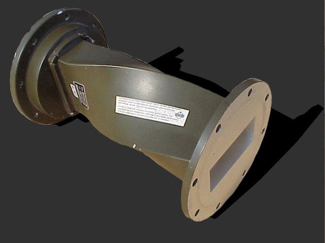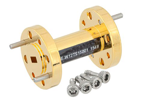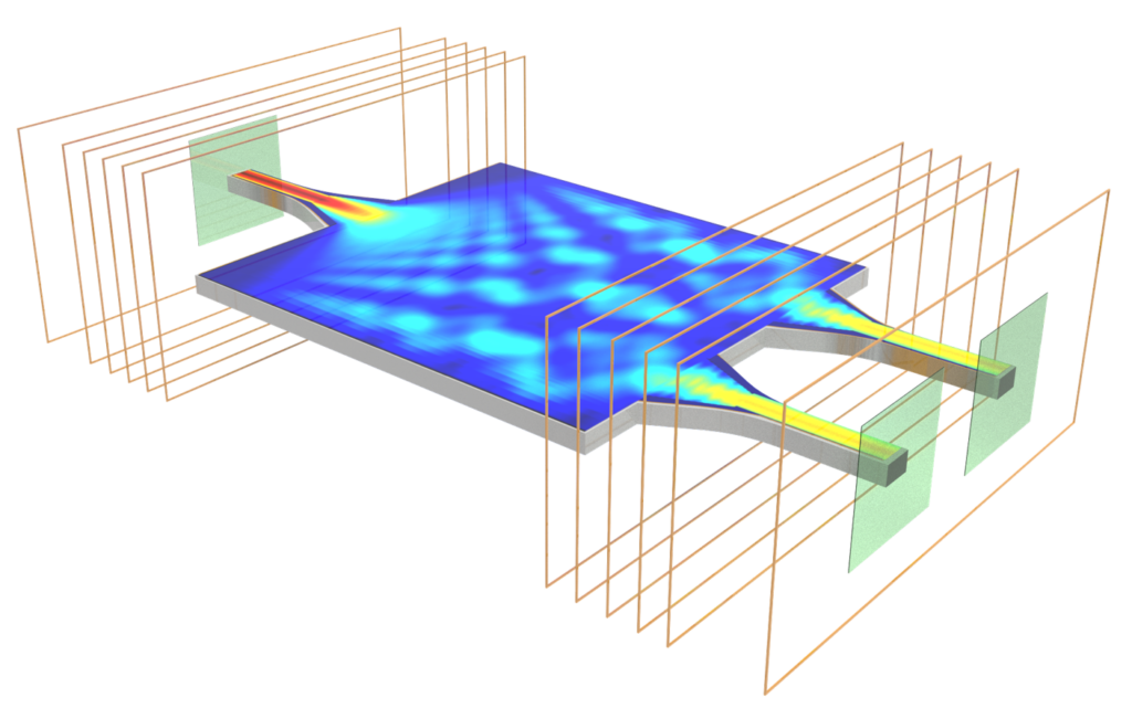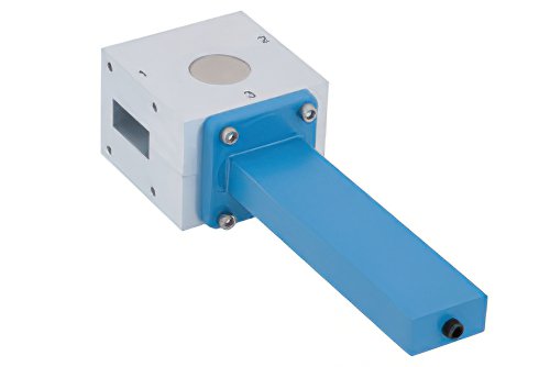
What Makes Waveguide Tee Junctions Unique
Waveguide tee junctions achieve 98% power division accuracy with <0.5dB insertion loss at 18-40GHz. The E-plane (series) and H-plane (shunt) designs create unique phase characteristics – 180° shifts in E-tees vs 0° in H-tees. Precision milling maintains ±0.01mm flange alignment for VSWR <1.25 in 5G mmWave systems. Principle of T-Junction At 3 AM, alarms suddenly […]
What Makes Waveguide Tee Junctions Unique Read More »