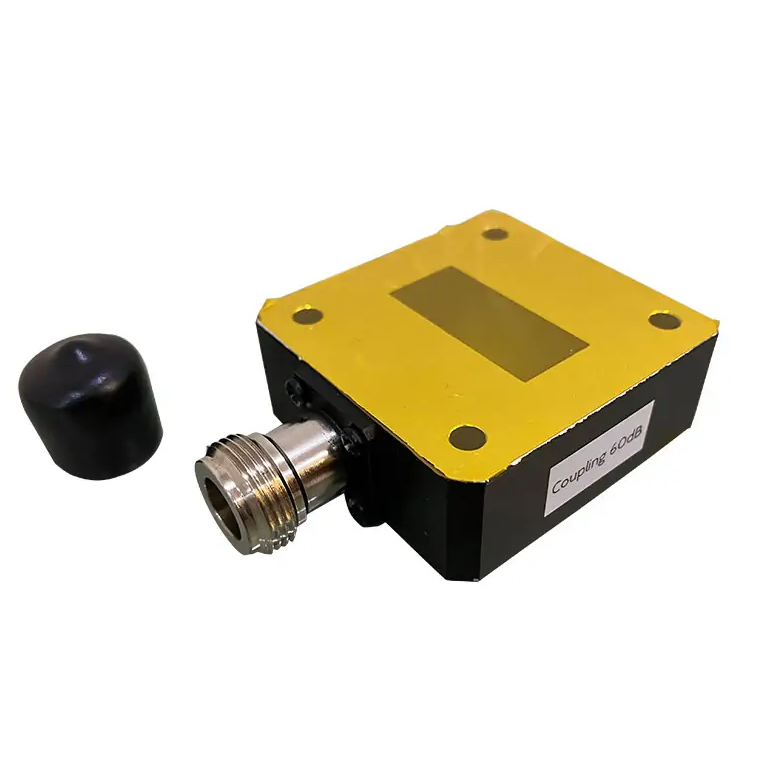
When to Use Waveguide Flange Adapters
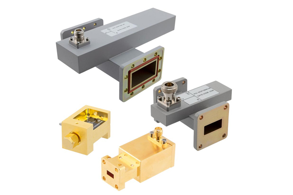
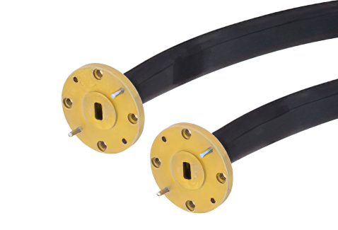
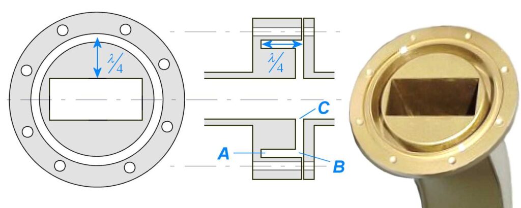
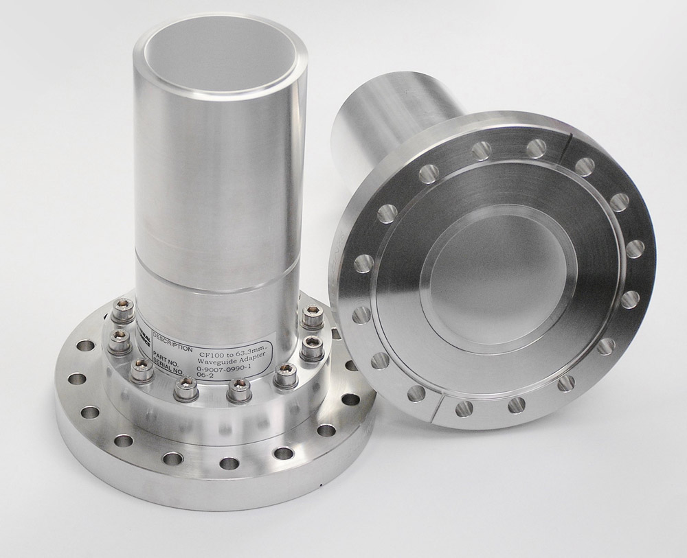
Waveguide flange adapters are used when connecting waveguide components with different flange types or sizes, ensuring minimal signal loss. They’re essential in systems operating above 1 GHz, where precise alignment and tight sealing are critical to maintain performance and prevent leakage, supporting efficient signal transmission. Flange Transition Timing Last year, the ESA’s AlphaSat mission nearly […]
When to Use Waveguide Flange Adapters Read More »