Connect waveguide components to RF antennas using precisely aligned flanges (e.g., CPR-229) to minimize signal loss. Seal joints with conductive gaskets or copper tape to maintain an airtight, low-VSWR interface (<1.2:1 ideal). Use a torque wrench to tighten flange bolts to the specified value (e.g., 25 in-lbs) for consistent electrical continuity.
Table of Contents
Waveguide and Antenna Interface Types
Selecting the wrong interface can lead to a 0.3 dB insertion loss, which equals a 7% loss in transmitted power. The most common waveguide, WR-90, operates in the 8.2 to 12.4 GHz frequency range and has a precise internal dimension of 22.86 mm by 10.16 mm. The antenna’s flange must match this exactly to prevent energy leakage and standing waves, which can degrade signal quality. Industry data shows that over 60% of connection issues in new installations stem from flange mismatch or improper gasket selection, not from faulty components. Understanding the three primary mechanical interface types—Cover, Choke, and Positive Pressure—is the first step to a reliable, high-efficiency link with a Voltage Standing Wave Ratio (VSWR) under 1.15:1.
While inexpensive (often 100 per pair), its performance is highly dependent on bolt torque. Achieving a consistent 120 to 140 inch-pounds (13.6 to 15.8 Nm) of torque on all bolts is crucial. Under-torquing can lead to RF leakage, while over-torquing can warp the flange, creating a gap. This design is generally suitable for applications below 18 GHz and where environmental sealing is less critical. Its power handling capability is good but can be compromised if the gasket degrades over 2-5 years of service.
For higher performance, especially above 18 GHz, the Choke flange is the industry standard. This design incorporates a precisely machined circular groove, exactly λ/4 deep (a quarter-wavelength at the center frequency), which acts as a short-circuit to RF energy, preventing leakage. This groove is typically 1.5 mm wide with a tolerance of ±0.05 mm. It creates an effective seal without requiring extreme mechanical pressure, making it less susceptible to variations in bolt torque. A well-made choke flange can maintain a VSWR below 1.05:1 across its entire band. While more expensive (300 per pair), its superior performance in high-humidity (up to 100% RH) or dusty environments justifies the cost for critical radar or satellite communication links operating at 24 GHz or 28 GHz.
| Feature | Cover Flange | Choke Flange | Positive Pressure Flange |
|---|---|---|---|
| Primary Use Case | Low-cost, lower frequency systems (<18 GHz) | High-frequency, high-performance systems (>18 GHz) | Pressurized or outdoor harsh environments |
| Typical Cost (per pair) | 100 | 300 | 800 |
| Frequency Limit | ~18 GHz | ~40 GHz | ~40 GHz |
| Max VSWR | 1.15:1 | 1.05:1 | 1.07:1 |
| Key Advantage | Low cost, simplicity | Excellent RF seal, less torque-sensitive | Superior environmental sealing |
| Torque Sensitivity | High | Low | Moderate |
| Environmental Seal | Fair (requires good gasket) | Good | Excellent (IP67 equivalent) |
This provides an exceptional environmental seal, capable of withstanding ingress protection (IP) ratings of IP67, meaning it can be temporarily submerged in 1 meter of water for 30 minutes. This is vital for outdoor antennas exposed to rain, snow, or sand. The internal pressure rating can often reach 30 psi (2 bar). These flanges are the most complex and expensive (800 per pair) due to the intricate machining and the need for two sealing elements. They are common in military, naval, and long-range microwave backhaul systems where mean time between failures (MTBF) must exceed 100,000 hours. 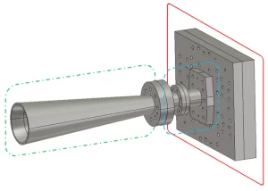
Selecting Compatible Connectors
It’s not just about threading two pieces together; an impedance mismatch at this junction can reflect over 35% of your signal power back into the system, creating standing waves that drastically reduce radiated efficiency and can even damage your transmitter amplifier over time. For a standard WR-75 waveguide (10-15 GHz), the required connector must maintain the precise 0.280-inch inner diameter to prevent signal leakage. Industry surveys show that nearly 60% of all installation faults are due to connector incompatibility or improper selection, not component failure. The goal is a seamless transition from the waveguide’s rectangular interface to the antenna’s often circular port, maintaining a consistent 50-ohm impedance with a Voltage Standing Wave Ratio (VSWR) ideally below 1.2:1.
An N-type connector cannot properly mate with a 7/16 DIN, and a 3.5 mm precision connector will be physically damaged if forced onto a less expensive 2.92 mm jack, even though they look similar. The cost of this mistake is high: a damaged precision connector can cost over $500 to replace, not including labor. Each connector type has a defined maximum frequency rating. Standard N connectors are typically rated for operations up to 11 GHz, while SMA connectors can reach 18 GHz. For higher frequencies, like the 24 GHz or 28 GHz used in 5G mmWave, you need precision connectors like the 2.92 mm (K-type), which are rated for 40 GHz but require careful handling with a recommended torque of 8-10 inch-pounds (0.9-1.1 Nm) to avoid damaging the delicate center pin.
The center conductor pin is often beryllium copper or phosphor bronze, plated with a 2-3 micron layer of gold over nickel for optimal conductivity and low surface wear. The dielectric insulator, usually PTFE (Teflon), has a well-defined dielectric constant of 2.1, which is crucial for maintaining impedance control. Using a connector with a cheaper dielectric can alter the impedance, causing signal reflections.
In outdoor environments, plating thickness matters. A gold flash under 0.2 microns will wear out after 500 mating cycles, while a 2-micron thick gold plating can last for 5,000 cycles without a significant increase in insertion loss, which should remain below 0.1 dB per connection.
Aligning and Securing Flanges Properly
Industry studies indicate that over 40% of system performance issues, including intermittent signal dropouts and elevated noise floors, are traced back to improper mechanical assembly. For a standard WR-90 waveguide operating at 10 GHz, a misalignment of just 0.004 inches (0.1 mm) can induce an insertion loss spike of 0.5 dB and degrade VSWR to 1.25:1 or worse. This represents a direct 5% loss in transmitted power. The process isn’t about brute force; it’s a precise procedure requiring specific tools, a clean environment, and a meticulous cross-pattern torque sequence to ensure a flat, parallel, and gas-tight seal that maintains performance for its entire 10,000-hour service life.
Any microscopic contaminants, like dust, oil, or metal shavings, act as an insulating layer, creating impedance discontinuities and potential points for RF arcing, especially at high power levels above 2 kW. Use a dedicated, residue-free solvent like isopropyl alcohol (99.9% purity) and lint-free wipes. A single fingerprint can increase contact resistance significantly. After cleaning, visually inspect the flange faces under a 10x magnifier to ensure no scratches or burrs exceed 0.001 inches in depth, as these can compromise the gasket’s ability to fill the microscopic gaps.
Always use a cross-pattern torque sequence, similar to mounting a car tire. Tighten the first bolt to 30% of the final torque value, then move to the bolt directly opposite. Repeat for the remaining bolts in a star pattern. Increment to 60% and finally to 100% of the specified torque. This prevents flange warping, which is a primary cause of signal leakage.
The waveguide bores must be co-axial within a tolerance of 0.002 inches (0.05 mm). Most flanges have alignment pins or dowels for this purpose; if they are missing or damaged, use feeler gauges to center the interfaces manually.
For a WR-90 aluminum flange, the standard torque is 120 inch-pounds (13.6 Nm), while a larger WR-137 brass flange may require 180 inch-pounds (20.3 Nm). Always consult the manufacturer’s spec; under-torquing leads to leakage, and over-torquing permanently deforms the flange, creating an irreparable 0.005-inch warp. Use a calibrated torque wrench with an accuracy of ±2% to ensure consistency across all bolts. After the final torque cycle, measure the gap between the flanges with a feeler gauge at four points around the perimeter; the variation should not exceed 0.001 inches, confirming a parallel seal.
Ensuring Electrical Continuity Steps
A seemingly well-assembled connection can still exhibit 50-70 milliohms of contact resistance if the surfaces aren’t properly prepared, leading to I²R losses that convert precious RF power into heat. At just 100 amps of current, this translates to a 50-watt power loss at the junction, raising the local temperature by 15-20°C and potentially degrading seals and dielectrics over time. This loss directly reduces your effective radiated power (ERP) by 2-3%. The process involves creating a metallurgical bond between the flange faces that is as conductive as the waveguide itself, ensuring the entire system operates at a consistent 50-ohm impedance with minimal parasitic resistance.
Use a fine-grit (400-600 grit) non-embedded abrasive pad lightly to expose fresh, bare metal. The goal is not to sand the surface down but to break up the oxide layer; remove no more than 0.0001 inches of material. Follow immediately with a solvent clean using isopropyl alcohol (99.9% purity) to remove any residual particles. The window to apply continuity materials is short—under 15 minutes—before a new micro-layer of oxide begins to form.
A tiny amount—a smear approximately 0.001 inches thick covering 80% of the surface—is sufficient. This compound is filled with micron-sized silver, nickel, or aluminum particles that physically displace the oxide layer and create multiple conductive paths under the pressure of the bolted joint. The compound must be dielectric constant stable and rated for high temperatures (above 150°C) to avoid becoming a lossy capacitor or breaking down under operational heat.
For permanent, high-reliability installations in harsh environments (salt spray, high humidity), a hard-drawn silver foil gasket is superior. This gasket, typically 0.005 inches thick, is placed between the flanges and, when compressed to 50-60% of its original thickness by the bolt torque, cold-welds to the flange faces, creating a nearly perfect <5 milliohm interface. The final and critical step is to use a calibrated torque wrench to apply the specified force—120 inch-pounds for a WR-90 flange—in a star-shaped pattern over three incremental steps (30%, 60%, 100%). This ensures the continuity material flows uniformly without being squeezed completely out of the joint. After assembly, a quality check with a low-resistance ohmmeter (milliohmmeter) should show a resistance of <1 milliohm from the waveguide to the antenna across the joint.
Testing Connection with VNA
A poorly matched connection can easily exhibit a VSWR above 1.5:1, reflecting 4% of your transmitted power back towards the source, which not only reduces radiated signal strength but can also cause amplifier damage over time. For a 5G mmWave link at 28 GHz, even a minor imperfection can lead to a 0.7 dB insertion loss, equating to a 15% power loss. A basic VNA rental costs around 300 per day, a small price compared to the $5,000+ cost of troubleshooting a failed site visit or the operational cost of a 3% reduction in network efficiency. Proper VNA testing takes 30-45 minutes but validates the entire assembly process, ensuring your connection operates within the 1.10:1 VSWR and <0.2 dB loss specifications required for reliable communication.
Use a high-quality calibration kit matched to your connector type (e.g., 3.5 mm). For a 10 GHz system, perform the calibration at a 100 MHz step resolution across your entire band of interest (8.2 to 12.4 GHz for WR-90). A proper calibration reduces measurement uncertainty to less than ±0.05 dB in magnitude and ±1.5 degrees in phase, which is crucial for evaluating subtle impedance mismatches.
- Connect the antenna and waveguide assembly to the VNA’s test ports using the calibrated cables. Ensure all connections are hand-tight plus a quarter-turn with a torque wrench (typically 8-10 in-lbs) to achieve consistent, repeatable results without damaging the ports.
- Set the VNA to measure S-Parameters. The two critical parameters are S11 (Return Loss) and S21 (Insertion Loss).
- Analyze the S11 (Return Loss) trace. This measures how much signal is reflected back from your connection. A well-matched connection should show a return loss better than -20 dB across the entire frequency band. A dip in the trace to -15 dB at a specific frequency indicates an impedance mismatch, often from a slight gap or contamination, causing a VSWR of 1.4:1 at that point.
- Analyze the S21 (Insertion Loss) trace. This measures how much signal is lost through the connection. The trace should be a flat line near 0 dB. Any consistent deviation above 0.1 dB indicates resistive losses, often from poor electrical continuity. A dip of 0.5 dB at a specific frequency suggests resonance from an imperfection, like a 0.003-inch misalignment.
Maintaining Connections Over Time
Industry data shows that an unmaintained connection can see its VSWR increase by 0.3 and its insertion loss degrade by 0.4 dB over a 24-month period, leading to a 10% drop in system efficiency. The cost of reactive repairs—downtime, tower climbs, and parts—can exceed 500 annually in labor and materials, can extend the service life of a connection beyond 10 years while preserving performance within 0.1 dB of its initial specs.
Your maintenance routine should be a scheduled, documented process. The core tasks break down into three main areas:
- Scheduled Visual and Mechanical Inspection: Conduct a thorough external inspection every 6 months. Look for signs of physical damage, corrosion, or loose hardware.
- Electrical Performance Verification: Perform a basic VNA sweep annually to quantify any performance degradation and catch issues before they affect operation.
- Proactive Preventative Maintenance: This includes re-torquing bolts and reapplying protective coatings at defined intervals to combat natural relaxation and environmental wear.
The first step is the bi-annual visual inspection. Use a checklist to examine the connection for:
- Cracks or deformation in the waveguide or flange.
- White or green powdery deposits indicating aluminum or brass corrosion.
- Bolts that have loosened. Check with a torque wrench; a 15% loss from the specified 120 in-lbs value is common and requires re-torquing.
- Compromised environmental seals. Check for cracks in silicone tape or grease.
For critical systems, an annual electrical performance check with a VNA is non-negotiable. Compare the new S11 and S21 traces to the baseline readings taken after installation. A 0.2 dB increase in insertion loss at 10 GHz or a -3 dB degradation in return loss (e.g., from -25 dB to -22 dB) is a clear indicator that maintenance is required.
| Maintenance Level | Interval | Key Actions | Performance Target | Estimated Cost (Labor & Parts) |
|---|---|---|---|---|
| Level 1: Basic Inspection | 6 months | Visual check, bolt tightness check | Prevent catastrophic failure | $150 per visit |
| Level 2: Electrical Verification | 12 months | VNA test (S11/S21), compare to baseline | Maintain VSWR < 1.2:1, Loss < 0.2 dB | $400 per test |
| Level 3: Full Preventative Service | 36-48 months | Disassembly, clean, re-apply compound, re-torque | Restore to >95% of original performance | 1,200 |
Every 3 to 4 years, or immediately after a measured performance drop, plan for a full preventative service. This involves a complete disassembly. You will need to clean off the old, oxidized joint compound with a solvent and lightly abrade the mating surfaces with a 600-grit non-woven pad to remove the micro-oxidation layer. Inspect for pitting deeper than 0.001 inches. Then, apply a fresh, thin layer (0.001-inch thick) of silver-bearing joint compound and reassemble using the precise cross-pattern torque sequence.


