Table of Contents
Catching Faint Satellite Signals
Satellite signals are incredibly weak by the time they travel 36,000 kilometers from orbit to your rooftop dish. A typical satellite transmission arrives on Earth with a power level of about 0.000000001 watts (one picowatt), which is over 10 billion times weaker than the signal from a local FM radio station. To put this into perspective, it’s often compared to trying to detect the heat from a 100-watt light bulb on the moon. This extreme weakness is the fundamental challenge that satellite antenna design must overcome. The primary tool for collecting enough of this faint energy is a parabolic dish, which acts like a funnel for radio waves, concentrating them onto a small receiver.
The entire principle of a satellite dish is based on collecting a massive amount of this weak signal energy over its large surface area and focusing it all onto a single, small point. A standard 60-centimeter (24-inch) Ku-band dish has a collecting area of roughly 0.28 square meters. This size is calculated to capture enough signal power to achieve a viable Carrier-to-Noise Ratio (CNR) above 6 dB, which is the minimum threshold for most digital receivers to lock onto and decode a signal. The dish’s parabolic shape is not arbitrary; every point on its surface reflects incoming parallel satellite waves inward toward the feed horn at the focal point. The precision of this curve is critical, with surface inaccuracies typically needing to be less than 1-2 millimeters to avoid scattering the signals and degrading performance.
The material of the dish itself is a key factor in its efficiency. Most modern dishes are made from pressure-molded aluminum or coated steel, materials chosen for their excellent RF reflectivity and durability. The reflectivity efficiency of a good dish can range from 55% to 70%, meaning that much of the captured signal energy is successfully directed to the feed horn and not lost. The feed horn, which is positioned at the precise focal point of the dish, acts as a waveguide. Its job is to neatly channel the concentrated bundle of microwaves into the Low-Noise Block downconverter (LNB) mounted directly behind it. The LNB’s first and most critical job is to amplify these incredibly faint signals. Using a Low-Noise Amplifier (LNA), it can boost the signal power by 40 to 50 decibels (dB), which is an amplification factor of 10,000 to 100,000 times, while adding the absolute minimum amount of electronic noise itself, often characterized by a noise temperature of 30 to 40 Kelvin. This initial amplification is what makes the signal strong enough for the subsequent stages of processing, transforming a whisper from space into a robust data stream.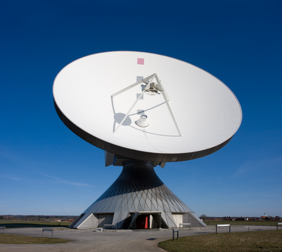
The Role of the LNB Converter
A typical satellite signal arriving at the LNB is centered around a high frequency range of 10.7 to 12.75 Gigahertz (GHz) and possesses a power level as low as -60 to -80 decibels relative to one milliwatt (dBm). Transmitting a signal this weak down a 100-foot coaxial cable to your indoor receiver would result in catastrophic loss; the cable itself would attenuate the signal by over 20 dB, effectively destroying it.
The first component the focused signal from the dish’s feed horn encounters inside the LNB is the Low-Noise Amplifier (LNA). This is a specialized semiconductor, often a Gallium Arsenide (GaAs) Field-Effect Transistor (FET), chosen for its ability to amplify signals while adding the absolute minimum amount of internal electronic noise. This noise performance is quantified as noise temperature, with high-performance LNBs operating between 28 K and 40 Kelvin. For every 1 Kelvin increase in this rating, the receiver’s ability to lock onto a weak signal measurably decreases. The LNA provides the initial critical gain of 40 to 50 dB, boosting the picowatt-level signal by a factor of 100,000 to a strength that can withstand the subsequent processing and cable run.
The amplified signal then moves to the mixer stage. Here, the high-frequency satellite signal (e.g., 11.700 GHz) is combined with a stable signal generated by the LNB’s internal local oscillator (LO). A standard LNB has two common LO frequencies: 9.75 GHz for the lower band and 10.60 GHz for the higher band. The fundamental principle of heterodyning occurs here; the mixer outputs the mathematical difference between the satellite frequency and the LO frequency. This process creates the Intermediate Frequency (IF) signal that is sent down the cable. For example, mixing an 11.700 GHz satellite signal with a 9.75 GHz LO produces an IF of 11.700 – 9.750 = 1.950 GHz (1950 MHz). This new L-band frequency range of 950 MHz to 2150 MHz is robust enough to be transmitted through 150 feet or more of RG-6 coaxial cable with relatively low loss of around -5 to -10 dB.
Modern LNBs are often Universal LNBs, which means they handle the entire Ku-band spectrum by electronically switching between their two local oscillator frequencies. This switching is triggered by a 22 kHz tone sent from the satellite receiver over the same coaxial cable. A 13 Volt DC power supply from the receiver activates the LNB and selects vertical polarization, while 18 Volts DC selects horizontal polarization. This combination of commands allows a single LNB and cable to deliver a wide range of channels. The entire unit is housed in a sealed, weatherproof enclosure to protect its sensitive electronics from moisture and temperature extremes ranging from -40°C to +60°C, ensuring an operational lifespan of over 10 years.
Aiming the Dish at the Satellite
Precisely aligning a satellite dish is a geometric challenge that requires calculating its exact orientation relative to your specific location on Earth and a satellite orbiting 35,786 km away in geostationary orbit. The alignment is defined by three angles: azimuth (compass direction), elevation (tilt up from horizontal), and polarization (skew). For example, aiming at the SES-3 satellite at 103° West from Denver, Colorado requires an azimuth of 191.5 degrees true north and an elevation of 38.2 degrees. An error of just 0.2 degrees in elevation can result in a signal loss of over 30%, dropping the Carrier-to-Noise Ratio (CNR) below the 6 dB lock threshold and making the picture pixelate or disappear entirely. This process demands careful measurement and fine-tuning, as the satellite’s signal footprint is often only 100-200 miles wide on the ground, making the dish’s beamwidth incredibly narrow.
The first step is obtaining your precise latitude and longitude coordinates, which can be sourced from a smartphone GPS with an accuracy of ±3 meters. These coordinates are plugged into an online calculator or a satellite pointing app to generate the three critical angles. The azimuth is the compass heading; a miscalculation of 5 degrees can completely miss the satellite. The elevation angle is perhaps the most sensitive; a standard 45 cm offset dish has a 3 dB beamwidth of approximately 2.5 degrees. This means if the satellite is at 30 degrees elevation, the dish will lose half its signal strength if it’s tilted to 28.75 or 31.25 degrees. This is why initial setup requires an inclinometer or a smartphone angle app calibrated to within ±0.1 degrees to set the elevation bracket accurately.
The final critical adjustment is the LNB polarization skew, often the most overlooked parameter. For a circular polarity satellite like Dish Network or DirecTV, this rotation is essential for aligning the LNB’s internal probe with the signal’s polarization. From a given location, this angle can range from -30 to +30 degrees. An incorrect skew of 15 degrees can degrade signal quality by 5 dB or more, as the LNB fails to properly isolate the vertically and horizontally polarized transponders, leading to interference and channel loss.
A basic meter might only show a 0-100% power scale, while a professional meter displays the true CNR in dB, which is far more accurate. The installer slowly sweeps the dish ±5 degrees in azimuth and elevation around the calculated position, watching for the meter’s peak reading. The goal is to maximize the Signal-to-Noise Ratio (SNR), not just raw power. A good alignment for a DTH service like DirecTV will typically yield a CNR of at least 10 dB and a received power level of -55 to -65 dBm on a transponder. Final micro-adjustments of 0.1 degrees are made to find the absolute peak, after which all bolts are tightened securely to prevent wind from shifting the alignment, which can occur with as little as 15 km/h gusts on a poorly secured mount. The entire process from setup to peak signal can take an experienced installer 15-20 minutes, but a novice may require 60-90 minutes of meticulous adjustment.
Parabolic vs. Flat Panel Antennas
A standard 60 cm (24-inch) offset-fed parabolic dish typically achieves a gain of 37.5 dBi at 12 GHz, with an efficiency rating of 65-70%. In contrast, a similarly sized flat panel antenna, which uses an array of embedded elements, might achieve a gain of only 33 dBi at the same frequency, with an efficiency of 40-50%. This 4.5 dBi difference translates to a significant 64% reduction in effective signal capture capability, making the parabolic design the undisputed champion for weak signal reception in fringe areas or for smaller sizes.
The core of the parabolic antenna’s advantage is its physical geometry. The dish’s surface area directly determines its gain. The gain of a parabolic reflector can be calculated using the formula: G = η(πD/λ)², where η is the efficiency, D is the diameter, and λ is the wavelength. For a 70% efficient 60 cm dish receiving a 12 GHz signal (λ=2.5 cm), the gain calculates to roughly 37.5 dBi. This high gain is crucial for receiving from satellites that have low Equivalent Isotropically Radiated Power (EIRP) in your area, often below 48 dBW. Flat panel antennas, often based on printed circuit board (PCB) technology with arrays of patch antennas, struggle to match this efficiency. Their gain is limited by the number of elements that can be packed into the area; a typical 40 cm x 40 cm panel might contain a 16×16 (256) element array. Each element’s small size results in lower individual gain, and the combined output, while coherent, cannot overcome the physics of a focused parabolic reflector. Their efficiency is lower due to dielectric losses in the PCB substrate and coupling losses between the densely packed elements.
| Parameter | Parabolic Dish (60 cm) | Flat Panel Antenna (40×40 cm) | Impact |
|---|---|---|---|
| Peak Gain | 37.5 dBi | 33 dBi | Parabolic provides ~64% more effective signal capture. |
| Aperture Efficiency | 65-70% | 40-50% | Parabolic uses its physical area much more effectively. |
| 3-dB Beamwidth | ~2.5 degrees | ~4.5 degrees | Parabolic has a narrower, more focused beam for better satellite discrimination. |
| Wind Load | High (>0.4 m² area) | Low (<0.2 m² area) | Flat panel offers ~50% less wind force, simplifying mounting. |
| Weight | 3.5 – 5 kg | 1.5 – 2.5 kg | Flat panel is typically 40-50% lighter for easier handling. |
| Depth / Profile | 45-60 cm deep | 3-5 cm deep | Flat panel is >90% slimmer, crucial for aesthetic installations. |
| Typical Cost | 80 | 250 | Parabolic dishes are ~60-70% cheaper for equivalent size. |
In a region where the satellite signal strength is marginal, a parabolic dish might achieve a Carrier-to-Noise Ratio (CNR) of 10 dB, providing a stable, rain-faded-resistant picture. A flat panel in the same location might only achieve a 6.5 dB CNR, placing it right on the cliff edge where the digital signal begins to break up with slight cloud cover or other minor attenuation. Consequently, parabolic dishes remain the default for direct-to-home (DTH) television, very small aperture terminal (VSAT) data links, and any critical communication where reliability is paramount. The primary advantage of the flat panel is its ultra-low profile and significantly reduced wind load of <0.2 m², making it ideal for urban apartments, RVs, and structures where a large dish is impractical or prohibited by homeowners’ associations. They are also easier to mount and align due to their wider beamwidth. The choice ultimately boils down to the user’s location relative to the satellite’s beam strength and the priority placed on performance versus aesthetics and installation constraints.
Sending Data Back to Satellite
Transmitting data from a small ground station back to a satellite orbiting 35,786 km away presents a formidable engineering challenge. The key obstacle is the immense path loss, which exceeds 200 decibels (dB) at Ku-band frequencies. To overcome this, a user terminal must generate a powerful, highly focused signal. A typical consumer-grade VSAT uplink operates in the 14.0 – 14.5 GHz band and transmits with a power of 2 watts from the Block Upconverter (BUC), a specialized outdoor amplifier. Combined with a 60 cm dish’s gain of 37.5 dBi, this creates an Effective Isotropic Radiated Power (EIRP) of roughly 51.5 dBW. This powerful, focused beam must be aimed with an accuracy of better than 0.2 degrees to successfully hit the satellite’s receive antenna, a task managed by the modem and a sophisticated tracking system.
The heart of the transmit chain is the Block Upconverter (BUC), which is mounted on the dish’s arm opposite the LNB. It performs the inverse function of the LNB. The modem inside the home sends it a low-power Intermediate Frequency (IF) signal in the L-band range of 950-1450 MHz. The BUC first amplifies this signal, then uses an internal local oscillator (LO) at 13.05 GHz to upconvert it to the final 14.0-14.5 GHz transmission frequency. This high-frequency signal is then amplified to its final output power. Consumer BUCs are typically rated at 2 W (+33 dBm), while enterprise systems can use 4 W, 8 W, or even 16 W (+42 dBm) units to achieve a higher EIRP and thus a faster data return rate. The BUC’s efficiency is critical; a 2 W BUC might draw 24 watts of DC power from the modem, meaning only ~8% of the energy is converted into RF power, with the rest wasted as heat, which is dissipated through a large finned heatsink.
The absolute non-negotiable requirement for a stable uplink is precise antenna pointing. A pointing error of just 0.5 degrees can reduce the EIRP at the satellite by 3 dB, effectively cutting the transmitted power in half. This can be the difference between a stable 512 kbps return link and a completely non-functional connection. Modern systems often use automatic pointing systems or highly accurate manual alignment aided by the modem’s diagnostic page, which reports the received satellite beacon strength to verify the dish is perfectly aimed.
It uses a TDMA (Time Division Multiple Access) scheme, which allows thousands of user terminals to share the same satellite transponder frequency by transmitting in short, assigned time slots. The modem must precisely synchronize its transmissions with the network hub, with timing accuracy measured in microseconds. It also constantly adjusts the modulation and coding (ModCod) scheme based on link conditions. In clear weather, it might use 16APSK modulation with ¾ coding for high spectral efficiency, yielding a return link speed of 750 kbps. During rain fade, it might automatically fall back to a more robust but slower QPSK modulation with ½ coding, reducing speed to 350 kbps but maintaining the critical link.
| Uplink Component / Parameter | Typical Specification / Value | Functional Importance |
|---|---|---|
| BUC Output Power | 2 W (+33 dBm) | Primary factor determining uplink strength; higher power enables higher data rates. |
| BUC DC Power Draw | 24 W @ 2 W RF out | Indicates power consumption and inefficiency; requires adequate power supply from modem. |
| Uplink Frequency Band (Ku) | 14.0 – 14.5 GHz | Standard band for consumer VSAT return links; requires appropriate licensing. |
| Transmit Modulation (ModCod) | QPSK to 16APSK | Adaptive modulation balances speed and robustness against rain fade and other losses. |
| EIRP (60cm dish + 2W BUC) | ~51.5 dBW | The final measure of effective power radiated towards the satellite. |
| Pointing Accuracy Requirement | < 0.2 degrees | Critical for maximizing EIRP; mispointing is a primary cause of uplink failure. |
| Return Link Data Rate | 256 kbps – 1.5 Mbps | The actual achievable speed, heavily dependent on EIRP, modulation, and service plan. |
| BUC Operating Temperature | -30°C to +60°C | Must operate reliably in extreme outdoor environmental conditions. |
Exceeding the authorized EIRP limit of 52 dBW for standard consumer terminals can result in the hub station automatically commanding the user’s modem to reduce its power or even temporarily disable transmission to protect the satellite’s sensitive receivers. The cost of the uplink components is significant; a quality 2 W BUC can range from 500, representing a major portion of the total hardware cost for a two-way VSAT system, which often exceeds $2000 before installation.


