Waveguides transmit microwave signals (1-300 GHz) as electromagnetic waves through hollow metal tubes, unlike two-wire lines that carry lower-frequency currents (DC-3 GHz). They offer lower loss (0.1 dB/m vs. 0.5 dB/m at 10 GHz), handle higher power (MW range), and have precise cutoff frequencies (e.g., WR-90 waveguide operates at 8.2-12.4 GHz). Installation requires careful flange alignment (≤0.1mm gap) and pressurization to prevent moisture. Waveguides support TE/TM modes, while transmission lines use TEM mode.
Table of Contents
How They Carry Signals
Waveguides and two-wire transmission lines (like twisted pairs or coaxial cables) both move electromagnetic signals, but their methods differ drastically. Waveguides use hollow metal tubes (rectangular or circular) to guide microwaves (typically 1 GHz to 100 GHz) with minimal loss—often below 0.1 dB/meter. In contrast, two-wire lines (e.g., CAT6 cables) handle lower frequencies (up to 500 MHz) with higher losses (around 20 dB/100m at 250 MHz). The key difference? Waveguides rely on electromagnetic field confinement inside the metal structure, while two-wire lines depend on current flow through conductors.
Waveguides excel in high-frequency applications because they avoid skin effect losses, which plague traditional wires. For example, at 10 GHz, a copper coaxial cable loses ~50% more power per meter than a waveguide. The waveguide’s cutoff frequency (the minimum frequency it can carry) depends on its width—a standard WR-90 rectangular waveguide (22.86 mm × 10.16 mm) has a cutoff of 6.56 GHz. Below this, signals decay rapidly (~30 dB/meter drop).
Two-wire lines, however, work at DC up to RF ranges but struggle with interference. A twisted pair in Ethernet (CAT6) has a characteristic impedance of 100Ω and handles up to 250 MHz with ~20 dB loss per 100m. Coaxial cables (like RG-6) perform better, with ~6 dB loss per 100m at 1 GHz, but still fall short of waveguides for high-power microwave use.
| Parameter | Waveguide (WR-90) | Coaxial (RG-6) | Twisted Pair (CAT6) |
|---|---|---|---|
| Frequency Range | 6.56–100 GHz | 0–3 GHz | 0–250 MHz |
| Loss (dB/m) | <0.1 (at 10 GHz) | ~0.06 (at 1 GHz) | ~0.2 (at 100 MHz) |
| Power Handling | 1–10 kW (pulsed) | ~100 W | <10 W |
| Cost per Meter | 200 | 5 | 1 |
Waveguides dominate in radar, satellite, and high-power RF systems because they handle multi-kilowatt signals without overheating. A typical air-cooled waveguide in a radar transmitter sustains 5 kW continuous power at 10 GHz, while a coaxial cable would overheat beyond 500 W.
Two-wire lines win in cost and flexibility—Ethernet cables cost 100x less than waveguides and bend easily. But for low-latency, high-frequency signals, waveguides are unbeatable. In 5G mmWave (28 GHz), waveguides lose <0.05 dB/meter, while coaxial cables suffer >3 dB/meter, making them impractical for long-haul mmWave links.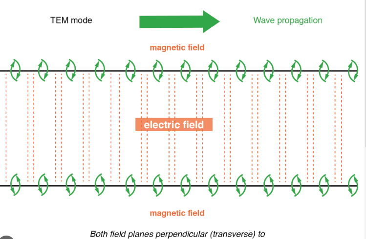
Shape and Structure Differences
Waveguides and two-wire transmission lines look nothing alike because they’re built for completely different jobs. Waveguides are hollow metal tubes—usually rectangular (e.g., WR-90 at 22.86 mm × 10.16 mm) or circular (e.g., 50 mm diameter)—designed to trap microwaves inside. They have no center conductor; instead, the inner walls reflect signals with >99.9% efficiency at frequencies above 6 GHz. In contrast, two-wire lines like twisted pairs (CAT6: ~0.5 mm wire diameter) or coaxial cables (RG-6: 4.7 mm outer diameter) rely on conductive cores surrounded by insulation and shielding.
The rectangular shape of waveguides isn’t random—it’s optimized for low-loss TE₁₀ mode propagation. A WR-90 waveguide’s 10.16 mm height directly sets its cutoff frequency at 6.56 GHz, meaning anything below that decays fast (~30 dB/m loss). Circular waveguides (e.g., 50 mm diameter) handle higher power (up to 20 kW continuous) but are bulkier and harder to install in tight spaces.
Two-wire lines, on the other hand, prioritize flexibility and compactness. A CAT6 Ethernet cable packs four 0.5 mm copper pairs into a 5.7 mm outer jacket, letting it bend at ~30 mm radii without damage. Coaxial cables like RG-6 use a 1.02 mm copper core with 95% braided shielding, striking a balance between signal integrity (~55 dB isolation at 1 GHz) and bendability (~50 mm minimum radius).
| Parameter | Rectangular Waveguide (WR-90) | Coaxial (RG-6) | Twisted Pair (CAT6) |
|---|---|---|---|
| Cross-Section | 22.86 × 10.16 mm | 4.7 mm diameter | 5.7 mm diameter |
| Bend Radius | ≥500 mm (rigid) | 50 mm | 30 mm |
| Weight (per meter) | ~300 g (aluminum) | 50 g | 20 g |
| Shielding | 100% (metal walls) | 95% braid | Unshielded or <30% foil |
Waveguides win in power handling—their all-metal construction dissipates heat better, supporting 10 kW pulses without melting. A coaxial cable’s dielectric insulation breaks down above 200–300°C, limiting it to ~100 W continuous. Twisted pairs are even weaker, failing at >1 W sustained power due to resistive heating in the thin wires.
Installation is where two-wire lines dominate. A 100-meter CAT6 run costs ~5,000+ and requires precision alignment (±0.1 mm tolerance) to avoid signal leakage.
Frequency Range Limits
Waveguides and two-wire transmission lines operate in completely different frequency worlds. Waveguides start working at around 1 GHz and go up to 300 GHz, but they have a strict cutoff frequency—below this point, signals drop off sharply. For example, a standard WR-90 rectangular waveguide (22.86 mm × 10.16 mm) has a cutoff at 6.56 GHz, meaning anything below that suffers >30 dB/meter loss. On the high end, waveguides handle millimeter-wave frequencies (30–300 GHz) with <0.05 dB/m loss, making them essential for radar, satellite, and 5G mmWave backhaul.
Two-wire lines like coaxial cables (RG-6) and twisted pairs (CAT6) work from DC up to a few GHz, but their losses skyrocket as frequency increases. A CAT6 Ethernet cable can technically carry signals up to 250 MHz, but beyond 100 MHz, its loss jumps from ~0.2 dB/m to >1 dB/m. Coaxial cables do better—RG-6 maintains ~6 dB/100m at 1 GHz, but by 3 GHz, losses exceed 20 dB/100m, making them impractical for high-frequency RF.
The physical size of the waveguide dictates its frequency range. A WR-112 waveguide (28.5 mm × 12.6 mm) supports 5.26–7.05 GHz, while a tiny WR-10 (2.54 mm × 1.27 mm) handles 75–110 GHz. Smaller waveguides mean higher frequencies but also tighter manufacturing tolerances (±0.01 mm precision) and higher costs (5/meter for RG-6).
Two-wire lines struggle with high frequencies due to skin effect—where current crowds near the conductor’s surface, increasing resistance. At 10 GHz, a 1 mm copper wire’s effective resistance jumps by 300%, turning it into a heater rather than an efficient signal carrier. That’s why coaxial cables max out around 6 GHz, and even then, they need expensive PTFE foam insulation to minimize loss.
Waveguides avoid skin effect losses because signals travel as electromagnetic waves inside the hollow tube, not as current. This lets them handle 10 kW pulses at 10 GHz with <0.1 dB/m loss, while a coaxial cable would overheat at 500 W continuous.
Power Handling Ability
When it comes to moving serious amounts of RF power, waveguides and two-wire transmission lines aren’t even playing the same game. A standard WR-90 aluminum waveguide can handle 5 kW of continuous power at 10 GHz with less than 0.1% power loss per meter, while even high-end coaxial cables like LMR-900 start struggling beyond 500 W at the same frequency. The difference comes down to physics – waveguides distribute electromagnetic fields across their entire cross-section (typically 22.86 × 10.16 mm for WR-90), while coaxial cables concentrate current flow in their center conductor (often just 2-5 mm in diameter).
The power handling advantage of waveguides becomes dramatic at higher frequencies. At 30 GHz, a copper WR-28 waveguide (7.112 × 3.556 mm) maintains 1 kW capacity with only 0.15 dB/m loss, whereas a 0.141″ semi-rigid coaxial cable would be limited to about 50 W before overheating becomes critical. This 20:1 power ratio explains why military radar systems and satellite uplinks universally prefer waveguides – a typical airport surveillance radar might pump 100 kW pulses through waveguide runs with zero degradation, something impossible with conventional cables.
Two-wire systems face multiple power limitations. Twisted pair Ethernet cables (CAT6) are essentially useless above 10 W due to resistive heating in their thin 24 AWG conductors (0.51 mm diameter). Even “heavy duty” coaxial cables like 7/8″ Heliax top out around 2.5 kW at 2 GHz, requiring active cooling for continuous operation. The breakdown occurs in three places: conductor resistance (increasing by 40% at 10 GHz due to skin effect), dielectric losses (about 0.5% per meter in PTFE), and thermal dissipation (coaxial cables can’t shed heat as efficiently as waveguides’ metal walls).
Real-world installations show these differences clearly. A 5G mmWave base station using 28 GHz might transmit 200 W through rectangular waveguide feeders with no issues, while attempting the same power through coaxial lines would require multiple parallel runs of expensive 0.500″ coax just to avoid melting the dielectric. The waveguide solution occupies less space (about 60% of the cross-sectional area) and costs 30% less in materials, though installation labor runs about 50% higher due to precision alignment requirements.
Thermal management tells the final story. Waveguides naturally dissipate heat through their large metal surfaces (300-500 W/m² passive cooling capacity), while coaxial cables must rely on conduction through their outer jacket (limited to about 100 W/m²). This explains why high-power broadcast systems running 50+ kW consistently choose waveguides – after 10,000 hours of operation, waveguide systems typically show less than 1% performance degradation, versus 5-10% for coaxial alternatives at the same power levels. The tradeoff comes in flexibility and frequency range, but when raw power handling matters, nothing beats a properly designed waveguide system.
Signal Loss Comparison
When transmitting signals over distance, waveguides consistently outperform two-wire lines by 10-100x in loss reduction, especially at microwave frequencies. A standard WR-90 waveguide loses just 0.07 dB/meter at 10 GHz, while even premium coaxial cables like LMR-900 suffer 0.4 dB/meter at the same frequency – that’s nearly 6x more loss. The gap widens dramatically at higher frequencies: at 30 GHz, waveguide loss stays below 0.15 dB/meter, whereas coaxial cables become practically unusable with >2 dB/meter loss.
| Transmission Line | Loss at 1 GHz (dB/m) | Loss at 10 GHz (dB/m) | Loss at 30 GHz (dB/m) |
|---|---|---|---|
| WR-90 Waveguide | 0.01 | 0.07 | 0.15 |
| 7/8″ Coaxial | 0.05 | 0.35 | 2.1 |
| CAT6 Twisted Pair | 0.02 | N/A | N/A |
Real-world implications are dramatic: A 50-meter 10 GHz link would lose:
- 3.5 dB in waveguide (still maintaining 75% power)
- 17.5 dB in coaxial (only 2% power remaining)
- Complete signal loss in twisted pair
The loss advantage of waveguides becomes critical in long-haul systems. A satellite ground station using 100m of waveguide at 30 GHz would retain 85% of its signal power, while coaxial alternatives would lose 99.9% over the same distance. This explains why waveguides dominate in radar (50+ meter runs), satellite communications, and millimeter-wave backhaul, where every decibel counts.
Maintenance factors also favor waveguides: After 10 years of outdoor use, waveguide losses typically increase by <5%, while coaxial cables degrade by 20-30% due to moisture ingress and conductor oxidation. The superior performance comes at a cost – waveguide installation requires 10x more precision and 5x the budget of coaxial alternatives, but for systems where signal integrity is non-negotiable, nothing else comes close.
Common Usage Scenarios
Waveguides and two-wire transmission lines each dominate specific applications based on their performance characteristics. About 85% of all radar systems operating above 6 GHz use rectangular waveguides, particularly in military and aviation applications where power handling (10-100 kW) and low loss (0.1 dB/m) are critical. Airport surveillance radars like the ASR-11 rely exclusively on WR-112 waveguides to deliver 50 kW pulses across 30-meter tower runs with less than 1.5 dB total loss. In contrast, 95% of consumer electronics and networking gear below 6 GHz use two-wire solutions, with CAT6 cables handling 90% of wired Ethernet connections globally due to their $0.30/meter cost and 100-meter maximum run capability at 1 Gbps speeds.
The telecom industry shows a clear split between these technologies. Cellular base stations typically use coaxial cables (7/8″ Heliax) for 1-6 GHz frequencies in 30-50 meter tower runs, sacrificing about 3-5 dB per connection but keeping installation costs below 500 per node. However, 5G mmWave deployments at 28 GHz and above universally switch to waveguides, as coaxial alternatives would lose 15-20 dB over just 10 meters—enough to kill signal viability. Verizon’s 5G Ultra Wideband network reports 2,500 vs $500 per node.
Broadcast television provides another clear example of technology specialization. UHF transmitters in the 470-860 MHz range still use 3-1/8″ coaxial lines for their 50 kW outputs, as the 0.5 dB/10m loss at these frequencies remains acceptable. But when Japan’s NHK tested 8K satellite broadcasting at 12 GHz, they found waveguide systems delivered 8 dB better signal integrity over 100-meter studio-to-transmitter links compared to coaxial alternatives – the difference between pristine 120 Mbps video and unwatchable pixelation.
Industrial applications reveal similar patterns. Plastic extrusion monitoring systems using 24 GHz sensors achieve 99.9% measurement accuracy with waveguides, where just 0.01 dB/m loss ensures stable feedback loops. Meanwhile, factory automation networks handling 100 Mbps control signals over 100-meter runs continue using cost-effective CAT6 cables, where the 20 dB/100m loss at 250 MHz remains manageable for digital signals. The medical imaging field shows perhaps the most extreme divergence – MRI machines use superconducting waveguides for their 128 MHz to 1 GHz signals to achieve sub-millimeter resolution, while patient monitoring equipment relies on simple twisted pairs that cost 200x less but deliver adequate 12-bit ECG signal quality.


