Waveguide bandwidth hinges on inner diameter (e.g., 3cm radius boosts TE₁₁ cutoff to 3.412cm, squeezing higher-mode onset), loss (TE₁₁ at 10GHz attenuates 0.015dB/m, narrowing usable range), and excitation purity—probes often stir multiple modes, unlike resonant couplers, trimming effective bandwidth by ~15%.
Table of Contents
Operating Frequency Cutoff
In a circular waveguide with a diameter of 2.54 cm (1 inch), you cannot simply send anyfrequency you want and expect it to propagate. The waveguide acts as a high-pass filter, meaning it has a strict lower limit called the cutoff frequency (). Below this specific frequency, signals attenuate rapidly, losing over 99% of their power within a few centimeters. For our 2.54 cm diameter waveguide, the cutoff frequency for the dominant TE11 mode is approximately 6.91 GHz. This isn’t a suggestion; it’s a physical law derived from the waveguide’s geometry. The relationship is precise:
The cutoff wavelength (λ_c) for the TE11 mode is λ_c = 3.41 * a, where ‘a’ is the radius of the waveguide in meters.
This translates directly to the cutoff frequency: or , where D is the diameter. This means bandwidth is fundamentally anchored to this cutoff point. You cannot have a functional bandwidth that includes frequencies below this threshold. The usable bandwidth for a single mode, typically defined as the range from 1.25f_c to 1.90f_c, is directly proportional to the cutoff frequency itself.
A larger diameter waveguide, say 5.08 cm (2 inches), would have a TE11 cutoff frequency of about 3.45 GHz, effectively shifting the entire usable bandwidth to a lower frequency range. This is a critical first step in design: selecting the waveguide diameter is synonymous with defining the absolute lowest frequency of operation, creating a ~4 GHz wide usable band starting from ~8.6 GHz for the 1-inch guide versus a ~2 GHz wide band starting from ~4.3 GHz for the 2-inch guide. The propagation constant changes dramatically near cutoff, with the wave impedance soaring to extremely high values, making efficient power transfer impossible. Operating even 5% below the calculated f_c results in a signal attenuation exceeding 100 dB per meter, rendering the waveguide useless for practical communication. 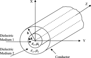
Waveguide Diameter Impact
A change in diameter doesn’t produce a linear effect; it triggers a cascade of inverse-square relationships that drastically alter the cutoff frequency, bandwidth potential, and signal loss. For instance, simply moving from a standard WR-75 rectangular guide (19.05 mm x 9.525 mm) to a circular guide with a comparable cutoff frequency requires a diameter of about 22.3 mm.
| Waveguide Diameter (mm) | TE11 Cutoff Frequency (GHz) ~1.84/D(cm) | Single-Mode Bandwidth (GHz) ~1.25f_c to 1.9f_c | Relative Attenuation (dB/m) at 2*f_c |
|---|---|---|---|
| 15.0 | 11.73 | ~14.67 – 22.29 | Base Reference (e.g., 0.5 dB/m) |
| 22.3 | 7.89 | ~9.86 – 14.99 | ~35% of 15mm guide’s attenuation |
| 30.0 | 5.87 | ~7.34 – 11.15 | ~15% of 15mm guide’s attenuation |
| 50.0 | 3.52 | ~4.40 – 6.69 | ~4% of 15mm guide’s attenuation |
The most immediate impact is on the cutoff frequency (), which has an inverse relationship with the diameter. The formula makes this crystal clear. If you double the diameter from 25 mm to 50 mm, the cutoff frequency is halved from 6.90 GHz to 3.45 GHz. This is a one-to-one inverse relationship. However, the more significant benefit for large-diameter guides comes from attenuation, which drops roughly with the cube of the diameter increase. The dominant loss mechanism in waveguides is ohmic loss in the walls. The power handling capability also sees a massive boost, increasing with the square of the diameter; a 50 mm diameter waveguide can handle approximately 4 times the peak power of a 25 mm guide because the cross-sectional area is larger. This makes larger diameters ideal for high-power radar systems operating at 10 kW to 1 MW peak power, where minimizing loss is critical over a 50-meter run, potentially saving hundreds of watts of wasted energy.
For a 30 mm guide, the single-mode bandwidth is about 3.81 GHz (from 7.34 to 11.15 GHz), but for a 50 mm guide, it’s only about 2.29 GHz (from 4.40 to 6.69 GHz). This increased risk of multi-mode operation is a major design constraint. Furthermore, the physical size and weight become significant factors. A 2-meter length of 50 mm diameter aluminum waveguide weighs approximately 5.5 kg, whereas a 30 mm diameter guide of the same length weighs only about 2.0 kg. This impacts the structural support needed, the cost of raw materials, which can vary from 500 per meter depending on precision and plating, and the overall system agility, especially in airborne or satellite applications where every kilogram of mass can cost over $10,000 to launch.
Dominant Mode Selection
In a circular waveguide, the dominant mode is the mode with the absolute lowest cutoff frequency. For circular waveguides, this is the TE11 mode. Its dominance isn’t arbitrary; it’s a direct result of physics, offering the widest possible single-mode bandwidth. However, other modes like TM01 or TE01 exist and can be purposefully excited for specialized applications. Each mode has a unique electromagnetic field pattern inside the guide, which directly translates to significantly different performance characteristics in terms of attenuation, power capacity, and polarization stability. The choice of mode effectively dictates the waveguide’s application profile, moving it from a general-purpose transmission line to a specialized component for high-power radar or long-distance, low-loss communication.
| Mode | Cutoff Wavelength (λ_c) / Diameter (D) | Relative Cutoff Frequency (Normalized to TE11) | Key Characteristic |
|---|---|---|---|
| TE11 | 3.41 * D | 1.00 (Lowest) | Largest bandwidth (~83% useful band) |
| TM01 | 2.61 * D | ~1.31 | Symmetric field, good for coupling |
| TE21 | 2.06 * D | ~1.66 | – |
| TE01 | 1.64 * D | ~2.08 | Attenuation decreases with frequency |
Selecting the TE11 mode is the default for over 90% of standard waveguide systems because it provides the largest usable bandwidth. For a 50 mm diameter guide, the TE11 cutoff is 3.45 GHz, and the next mode, TM01, starts at approximately 4.52 GHz. This creates a theoretical single-mode operating window of about 1.07 GHz. In practice, you operate in the center of this window, from about 4.0 GHz to 4.5 GHz, to avoid modal dispersion near the edges. The bandwidth efficiency of the TE11 mode is approximately 83%, calculated as the ratio of its maximum usable frequency (1.9f_c) to its cutoff frequency. The primary drawback of TE11 is its attenuation, which, while low, follows the conventional pattern of decreasing with the square root of frequency increase. For a 3-meter long copper waveguide at 10 GHz, TE11 attenuation might be around 0.05 dB/meter.
In contrast, the TM01 mode has a 30% higher cutoff frequency than TE11, which immediately reduces the available bandwidth for a given diameter. Its primary advantage is its symmetric electric field pattern, which is useful in certain antenna feed systems like a parabolic reflector feed where a symmetrical pattern is desired. However, its attenuation is generally higher than TE11’s at the same frequency, making it less efficient for transmission over distances exceeding 10 meters.
Wall Material and Conductivity
The efficiency of this pathway, dictated by the material’s conductivity, directly controls a key performance metric: signal attenuation. Higher conductivity means less electrical resistance, which translates directly into lower signal loss per meter. This isn’t a small effect; the difference between ordinary aluminum and high-purity copper can result in a 30% increase in attenuation for the same waveguide dimensions. The choice of material is a fundamental trade-off between performance, cost, weight, and environmental durability.
- Aluminum (6061-T6): Conductivity is approximately 50% IACS (International Annealed Copper Standard), with a material cost roughly 40% lower than copper and a density of 2.7 g/cm³.
- Copper (C10100): Conductivity is 100% IACS, offering the benchmark for performance, but with a density of 8.96 g/cm³ and a material cost approximately 3-4 times higher than aluminum.
- Silver (Ag): Conductivity is about 105-108% IACS, providing a 3-5% attenuation improvement over copper, but at a cost that can be 50-100 times higher than aluminum, making it prohibitive for all but the most specialized applications.
The relationship between conductivity (σ) and attenuation (α) is inverse and square root: α ∝ 1/√σ. This means that to halve the attenuation, you need to quadruple the conductivity. Since bulk silver only offers a 5% conductivity gain over copper, it provides a negligible ~2.5% decrease in attenuation, which is often not cost-effective. The real-world impact is substantial over long runs. For a 30-meter long, 50 mm diameter waveguide operating at 10 GHz, using aluminum (50% IACS) might result in a total attenuation of 3.0 dB, meaning over 50% of the input power is lost. Switching to copper (100% IACS) would cut the loss to approximately 2.1 dB, preserving an additional 20% of the power at the output. For a 1 kW transmission system, this saving represents 200 watts of wasted heat in the aluminum guide versus 140 watts in the copper guide.
However, bare copper is soft and susceptible to oxidation, which can degrade its surface conductivity over a 5-10 year lifespan. Therefore, a common engineering practice is to use an aluminum waveguide body for its light weight and low cost—a 3-meter section might weigh 5 kg instead of 16 kg—and plate the interior with a 5-10 micron thick layer of electrodeposited copper. This achieves about 85-90% of the performance of solid copper at about 60% of the cost and 35% of the weight.
Manufacturing Tolerances Effect
A variance of just 0.05 millimeters in the internal diameter can shift the cutoff frequency by over 0.1 GHz and increase the Voltage Standing Wave Ratio (VSWR), leading to signal reflections and loss. In high-precision systems operating at 30-40 GHz, where wavelengths are less than 10 mm, the requirement for dimensional accuracy becomes extreme, often requiring tolerances tighter than ±0.025 mm to ensure predictable bandwidth and attenuation.
- Diameter Tolerance: A deviation of +0.1 mm in a 50 mm diameter guide can lower the TE11 cutoff frequency by approximately 0.07 GHz, potentially pushing the operating band too close to the cutoff of a higher-order mode.
- Ellipticity (Ovalness): A maximum diameter deviation of 0.2 mm from perfect circularity can degrade the polarization purity of the TE11 mode by 10-15 dB, causing unpredictable signal fluctuations.
- Surface Roughness: An RMS roughness increasing from 0.4 µm to 1.6 µm can increase attenuation by 5-8% and reduce the maximum power handling capacity by up to 15% due to localized field enhancement.
The most critical tolerance is the internal diameter consistency. The formula for cutoff frequency, , means that a +0.5% increase in diameter (e.g., from 50.00 mm to 50.25 mm) causes a -0.5% decrease in the cutoff frequency. For a guide designed to operate just above the TE11 cutoff at 4.0 GHz, this shift can move the operating point dangerously close to the high-loss cutoff region, increasing attenuation by 20% or more. Furthermore, this dimensional error alters the wave impedance, which must match precisely with the connected components like antennas or filters. A 2% impedance mismatch caused by a diameter error can create a VSWR of 1.1, leading to 0.5% of the power being reflected back towards the source. Over a system with 20 components, these small reflections accumulate, potentially causing 10% overall power loss and signal distortion.


