A gain antenna focuses RF energy directionally to enhance signal strength in target areas; e.g., a parabolic reflector with 20dBi gain (vs. ~2dBi for omni) uses its curved surface to concentrate waves, reducing dispersion and boosting range/clarity by 10x or more over isotropic radiators.
Table of Contents
Basic Idea of Antenna Gain
A common 2.4 GHz Wi-Fi router antenna might have a gain of about 2 dBi, similar to the light bulb. A high-gain directional antenna for the same frequency, like a panel antenna, can have a gain of 16 dBi or more, focusing the signal into a 30-degree wide beam that can extend the reliable range from a typical indoor range of 30 meters to over 150 meters in a clear line of sight.
Antenna gain is a measure of an antenna’s ability to direct radio frequency (RF) energy in specific directions, and it is fundamentally a trade-off between coverage area and signal distance. The core principle is conservation of energy. An antenna cannot create extra power; it can only redistribute the RF power it receives from the transmitter. A theoretical, perfectly omnidirectional antenna radiates power equally in all directions, forming a spherical pattern. This isotropic antenna is the reference point, with a gain of 0 dBi (decibels relative to isotropic). Real-world omnidirectional antennas, like a car’s AM/FM radio antenna, strive for a doughnut-shaped pattern, providing 360-degree coverage in the horizontal plane but with weaker signals above and below. A typical rubber ducky antenna for a 2.4 GHz wireless device might have a gain of 2 dBi.
A high-gain antenna, such as a Yagi-Uda antenna used for TV reception, acts like a lens. It takes the RF power that would have been radiated in unwanted directions (like upwards into the sky) and concentrates it into a narrower, more focused beam. For instance, an antenna with a gain of 10 dBi focuses the energy into a beam that might be 100 degrees wide. This focusing effect provides a significant advantage in the preferred direction. The increase in signal strength can be substantial. As a rule of thumb, every 3 dB increase in gain doubles the effective radiated power (ERP) in the main lobe of the signal. Therefore, a 9 dBi gain antenna effectively quadruples the power in its focused direction compared to the 0 dBi reference. This is why a satellite dish, with a very high gain of 30 dBi or more, can receive signals from a geostationary satellite 36,000 kilometers away by focusing on an incredibly narrow beamwidth of less than 2 degrees.
Gain describes the antenna’s directionality, not its amplification capability.
A small Wi-Fi patch antenna might be 10 cm x 10 cm with a gain of 8 dBi, while a large parabolic dish for microwave backhaul measuring 1.2 meters in diameter can achieve a gain of 38 dBi. The following table illustrates the practical difference between low and high-gain antennas in a typical 2.4 GHz ISM band application.
| Parameter | Low-Gain Omni Antenna (2 dBi) | High-Gain Directional Panel (16 dBi) |
|---|---|---|
| Typical Beamwidth | 360° (Horizontal) | 30° (Horizontal) |
| Best Use Case | Covering a single, large room (~150 sqm) | Point-to-point link over 500 meters |
| Relative Range Increase | 1x (Baseline) | ~6x (in the focused direction) |
| Physical Size (approx.) | 10 cm tall | 25 cm x 25 cm panel |
In practice, this means that replacing a 2 dBi omnidirectional antenna on an access point with a 16 dBi directional antenna pointed down a long hallway can increase the usable data rate at the far end by a significant margin, perhaps from a weak 6 Mbps connection to a strong 150 Mbps connection, because the received signal strength indicator (RSSI) improves from, say, -80 dBm to -65 dBm. This 15 dB improvement is a direct result of the antenna’s gain and focus, making the link far more reliable and faster.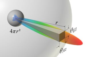
The Trade-off: Focus vs. Coverage
Imagine you need to provide Wi-Fi for a 50-meter wide warehouse. A single omnidirectional antenna with 3 dBi gain placed in the center might blanket the entire area, but the signal strength at the far ends, 25 meters away, could be weak, resulting in data speeds of perhaps only 20 Mbps.
Conversely, a high-gain 16 dBi panel antenna focused down the length of the warehouse could deliver a strong 300 Mbps connection to devices at the far end, but its narrow 30-degree beam would leave the sides of the building, just 10 meters to the left and right, with little to no signal. This trade-off is quantified by the antenna’s beamwidth—the angular measure of its coverage pattern—which shrinks predictably as gain increases.
A very low-gain, 0 dBi antenna has a theoretical beamwidth of 360 degrees. A common 9 dBi omnidirectional antenna might have a 360-degree horizontal pattern but compress the vertical pattern down to about 30 degrees, forming a flatter doughnut. Moving to a directional antenna, a 14 dBi Yagi antenna might have a beamwidth of 50 degrees, and a large 28 dBi parabolic dish narrows that to an extremely precise 10 degrees. This narrowing effect is the reason why proper alignment is critical for high-gain antennas; a dish with a 10-degree beamwidth that is misaligned by just 5 degrees can suffer a signal loss of over 50%. The benefit, however, is a massive increase in effective range. In a point-to-point wireless link, replacing 8 dBi antennas with 24 dBi dishes on both ends can increase the reliable communication distance from 2 kilometers to over 15 kilometers using the same transmitter power, because the energy is laser-focused rather than sprayed broadly.
For a home Wi-Fi router placed in a central location, a low-gain omnidirectional antenna is the correct choice because it provides blanket 360-degree coverage for multiple rooms. The signal might drop by 30% at the edges, but it reaches everywhere. For connecting two buildings 3 kilometers apart, a high-gain directional antenna is mandatory. The installation is more complex, requiring precise alignment that might take 30 minutes instead of 5, and the signal will be unusable for any device not directly in the path, but the link will be stable and high-speed.
How Gain is Measured: dBi
When you shop for antennas, you’ll see gain almost always listed as “dBi.” This three-letter acronym is the key to making accurate comparisons. A common rubber ducky antenna might be rated at 2.1 dBi, a Wi-Fi panel antenna at 9.5 dBi, and a large parabolic grid antenna for long-distance links at 24 dBi. But what does this actually mean? The “dB” stands for decibel, a logarithmic unit used to express a ratio, and the “i” specifies the reference point: an isotropic radiator. An isotropic radiator is a theoretical, perfect point source that radiates energy equally in all directions, forming a perfect sphere. It has a gain of 0 dBi by definition. Therefore, when an antenna is rated at 10 dBi, it means that in its direction of peak signal strength, it is 10 decibels more powerful than this theoretical isotropic radiator would be. Because the decibel scale is logarithmic, a 3 dBi increase represents a doubling of power intensity, a 10 dBi increase represents a tenfold multiplier, and a 20 dBi increase means a hundred times more power in the main lobe.
Understanding dBi requires grasping the logarithmic decibel scale, which is used to manage the immense range of signal powers encountered in radio work, from watts of transmission power to picowatts of received signals. A change of 3 dB represents a doubling or halving of power. So, an antenna with 6 dBi gain focuses four times the power (2 x 2) in its best direction compared to the 0 dBi isotropic reference. An antenna with 12 dBi gain provides 16 times the power density. This is why seemingly small numerical changes have a major practical impact. Replacing a 2 dBi antenna on an outdoor access point with a 10 dBi antenna doesn’t just make the signal “a bit better”; it increases the effective power in the beam’s direction by a factor of approximately 6.3 times (a 8 dB difference). This could be the difference between a unstable link with a received signal strength of -82 dBm and a robust connection at -74 dBm, potentially increasing data throughput by 50% or more by reducing errors. It is critical to distinguish dBi from another, older unit: dBd, which references a half-wave dipole antenna (which itself has a gain of about 2.15 dBi). A 10 dBi antenna is approximately 7.85 dBd. Most modern datasheets use dBi, and assuming a 0 dBi antenna is a common dipole is a frequent error that leads to a ~2 dB miscalculation of system performance.
| Feature | dBi (Decibels relative to Isotropic) | dBd (Decibels relative to Dipole) |
|---|---|---|
| Reference Antenna | Theoretical Isotropic Radiator (0 dBi) | Realistic Half-Wave Dipole Antenna (~2.15 dBi) |
| Gain Relationship | Standard, scientific reference. | Gain in dBd is always approx. 2.15 dB lower than in dBi. |
| Example | A 8 dBi panel antenna. | The same antenna would be rated as ~5.85 dBd. |
| Prevalence | Used in virtually all modern datasheets and specs. | Occasionally found in older documentation, e.g., TV antenna specs. |
When calculating the total system performance, known as the Equivalent Isotropically Radiated Power (EIRP), you add the transmitter power and the antenna gain, both expressed on a logarithmic scale. A router with a 20 dBm (100 milliwatt) output connected to a 9 dBi antenna produces an EIRP of 29 dBm. Regulatory limits, like the FCC’s 36 dBm EIRP limit for point-to-point links in the 5.8 GHz band, are based on this calculation. Therefore, understanding dBi is not just academic; it is essential for legal and efficient system design. A 3 dBi miscalculation in antenna gain could mean the difference between a compliant link and one that exceeds legal power limits by 100%.
Common High-Gain Antenna Types
While a standard omnidirectional antenna might offer a gain of 2-5 dBi, high-gain types start around 8 dBi and can exceed 30 dBi for specialized long-haul links. The choice depends on three factors: the required beamwidth for coverage, the necessary gain for distance, and the physical constraints of the installation site. For instance, covering a 90-degree sector of a parking lot requires a different antenna than establishing a point-to-point link over 5 kilometers. The most common types include panel antennas, Yagi antennas, parabolic dishes, and sector antennas, each with a distinct cost-to-performance profile ranging from a 500+ large dish.
- Panel Antennas: Flat, rectangular antennas ideal for short to medium-range directional coverage.
- Yagi-Uda Antennas: The classic “rooftop TV antenna” design, excellent for long-distance point-to-point links.
- Parabolic Dish Antennas: High-gain dishes that focus signals into an extremely narrow beam for very long distances.
- Sector Antennas: Designed to cover a wide horizontal arc, commonly used on cellular towers.
Panel antennas are the most common solution for directional Wi-Fi and cellular applications. They are typically flat, rectangular devices, often housed in a plastic radome, with dimensions around 20cm x 20cm for a 2.4 GHz model. Their gain typically ranges from 10 dBi to 16 dBi, with a horizontal beamwidth of 60 to 30 degrees and a vertical beamwidth of 40 to 20 degrees. This pattern is ideal for covering a specific area like a long hallway, a backyard, or a small business client from across the street. Their relative simplicity makes them cost-effective, with prices between 80. A key advantage is their front-to-back ratio, often 20 dB or higher, which means they reject interference from behind, a significant benefit in noisy urban environments. However, their gain is limited by their physical aperture; achieving gains beyond 18 dBi requires a panel over 60 cm in width, which becomes impractical.
A 10-element Yagi for the 2.4 GHz band might be about 60 cm long and provide a gain of approximately 14 dBi. Higher-gain Yagis with 18 elements can reach 17 dBi but extend to over 1 meter in length. Their beamwidth is generally narrower than a panel antenna, often around 50 degrees horizontally and 40 degrees vertically for a 14 dBi model. This makes them highly effective for bridging distances between 1 km and 10 km, but they require very precise alignment. A misalignment of just 10 degrees can result in a 3 dB signal loss, cutting the received power in half. Yagis are also more susceptible to wind load due to their larger surface area.
A 60 cm dish at 5.8 GHz can provide a gain of 28 dBi, while a 1.2 meter dish can achieve 34 dBi. This extremely high gain comes with an exceptionally narrow beamwidth; a 28 dBi dish has a beamwidth of only about 10 degrees. Aligning such a dish requires a signal meter and patience, as an error of just 2 degrees can degrade performance by 6 dB. Dishes are the go-to solution for licensed microwave backhaul links spanning 15 km to 50 km and for satellite communications. Sector antennas fill a different niche, designed to cover a wide horizontal arc, typically 90 or 120 degrees, with moderate gain of 12 dBi to 17 dBi. They are the workhorses on cellular towers, where three 120-degree sectors provide full 360-degree coverage. Their vertical beamwidth is intentionally narrow, around 10 degrees, to focus energy towards the ground and reduce interference, a concept called electrical downtilt.
Where High-Gain Antennas Are Used
Their value is realized in situations where a standard omnidirectional antenna fails, such as when a signal must travel more than 100 meters outdoors, penetrate a single wall with minimal loss, or serve a large, open area efficiently. For example, replacing a 3 dBi omni antenna on an outdoor access point with a 12 dBi sector antenna can increase the effective client capacity from about 25 devices to over 60 devices by focusing radiated power and reducing packet collisions.
- Extending Wireless Networks over Distance: Connecting buildings hundreds of meters to several kilometers apart.
- Improving Cellular and Fixed Wireless Reception: Boosting weak signals from distant cell towers for reliable voice and data.
- Enabling Long-Range Communications: Supporting critical links for public safety, aviation, and satellite ground stations.
- Focusing Coverage in Large Public Areas: Efficiently serving high-density client populations in stadiums or campuses.
The most common consumer-level application is in long-range Wi-Fi bridging. Two buildings located 500 meters apart can be connected using two 18 dBi parabolic grid antennas pointed directly at each other. This creates a stable point-to-point link capable of sustaining data rates over 200 Mbps, effectively sharing an internet connection. The total hardware cost for such a link can be under $300, a fraction of the monthly cost for a leased line. The installation requires precise alignment, often with a 2-degree tolerance, to achieve a signal strength better than -65 dBm. For serving a wider area, like a courtyard or parking lot, a 120-degree sector antenna with 14 dBi gain is mounted on a pole or roof. This antenna can provide coverage for a 200-meter radius, supporting dozens of users simultaneously because its vertical beamwidth of 10 degrees focuses energy towards the ground, reducing upward radiation waste and increasing overall system efficiency by up to 40% compared to an omni.
A rural home 8 kilometers from the nearest cell tower might receive a weak -110 dBm signal, insufficient for reliable data. A 16 dBi Yagi antenna mounted on a 6-meter mast and pointed precisely at the tower can improve the signal to a robust -85 dBm. This 25 dB improvement is the difference between an unusable connection and one capable of 20 Mbps downloads. The antenna’s narrow 40-degree beamwidth also provides 15 dB of rejection to interfering signals from other directions, increasing signal-to-noise ratio (SNR) and call quality. For maritime VSAT systems, a stabilized 60 cm parabolic dish with 36 dBi gain is required to maintain a link with a geostationary satellite 35,786 kilometers away while the vessel moves, providing internet where no cellular signal exists.
The primary indicator for a high-gain antenna is the presence of a clear, unobstructed line of sight to a specific target or over a defined coverage area.
These systems use 0.3 to 3 meter parabolic dishes operating in licensed frequency bands like 18 GHz or 23 GHz to achieve gains exceeding 40 dBi. A typical link spanning 15 kilometers between two radio towers can carry several gigabits per second of data with 99.999% (five-nines) reliability. The network latency for such a link is about 50 microseconds per kilometer, significantly lower than fiber optic cables, making it ideal for financial trading networks and utility grid control systems. The initial investment for a licensed microwave link is high, often 100,000, but the operational cost over a 10-year lifespan is lower than leasing equivalent bandwidth, with a typical ROI period of 24 to 36 months.
Choosing the Right Gain for You
The wrong choice can waste money and performance; for instance, installing a 24 dBi dish for whole-house Wi-Fi will create a strong but useless narrow beam, while using a 5 dBi omni to connect two buildings 1 km apart will result in a failed link. The decision starts by answering three questions: What is the straight-line distance to the target? Is the goal to cover a wide area or connect to a single point? And critically, is there a clear line of sight? A 10 dB improvement in the link budget, achievable by upgrading from a 3 dBi to a 13 dBi antenna, can more than double the reliable data rate at a distance of 100 meters.
- Short-Range Indoor Coverage (Under 20 meters): Low-gain omnidirectional antennas are usually sufficient.
- Long-Range Point-to-Point (Over 100 meters): High-gain directional antennas are essential.
- Wide Outdoor Area Coverage (90-120 degree sector): Sector antennas provide the best efficiency.
- Weak Signal Reception (Cellular, TV): Moderate-gain directional antennas maximize signal capture.
For a simple indoor Wi-Fi router in a 120 square meter apartment, the built-in omnidirectional antennas with a gain of 3 to 5 dBi are typically optimal. Their 360-degree horizontal coverage is ideal for devices in multiple rooms. Upgrading to a higher-gain omni, like a 7 dBi model, might seem beneficial, but it often flattens the vertical coverage pattern, potentially creating weak spots on floors directly above and below the router. The cost increase from 20 per antenna for minimal real-world benefit makes it an inefficient choice for this scenario.
A link spanning 500 meters between two buildings might require antennas with 15 dBi gain to maintain a strong connection. For a 2 km link, the required gain jumps to approximately 21 dBi, and for a 10 km link, you would need antennas with 27 dBi gain or higher. The following table provides a realistic starting point for common Wi-Fi frequencies, assuming standard 20 MHz channel bandwidth and 20 dBm transmit power.
| Scenario | Target Distance | Recommended Antenna Type | Typical Gain Range | Approx. Beamwidth | Key Consideration |
|---|---|---|---|---|---|
| In-Building Wi-Fi | < 20m | Omnidirectional | 3 – 5 dBi | 360° | Avoid high-gain omnis that create vertical dead zones. |
| Backyard/Patio Coverage | 50m | Sector or Panel | 10 – 14 dBi | 60° – 90° | Prioritize horizontal beamwidth to cover the area. |
| Point-to-Point Bridge | 1 km | Panel or Yagi | 16 – 20 dBi | 30° – 50° | Alignment is critical; narrower beamwidth increases difficulty. |
| Point-to-Point Bridge | 5 km | Parabolic Dish | 24 – 28 dBi | 10° – 15° | Requires professional installation and a very stable mount. |
You must also consider the legal limit on your system’s total output power, known as Equivalent Isotropically Radiated Power (EIRP). Regulatory bodies like the FCC set a maximum EIRP; for example, the 5.8 GHz UNII-3 band has a limit of 36 dBm. If your wireless transmitter outputs 23 dBm (200 mW), the maximum antenna gain you can legally use is 13 dBi (23 dBm + 13 dBi = 36 dBm EIRP). Exceeding this limit can result in interference and regulatory fines. Always calculate EIRP before purchasing a high-gain antenna.


