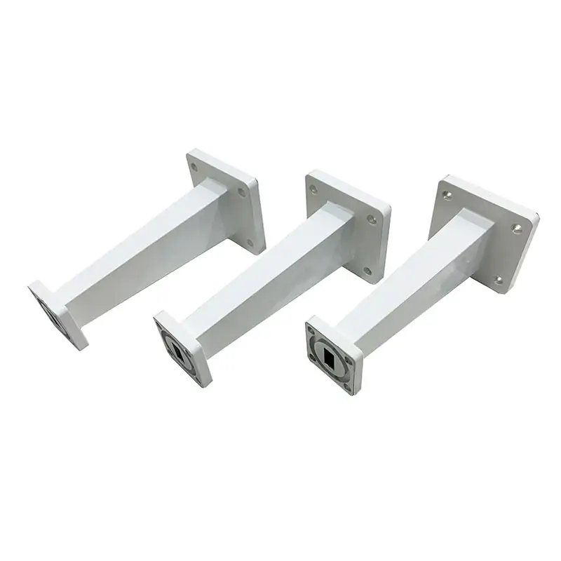
Waveguide Transitions
Waveguide transitions configured by the two waveguide interfaces, operating band, flange pair, finished length, material and installation envelope. Send both ends for drawing review.
Start with the two mating interfaces and the operating band.
Dolph Microwave supplies waveguide transition sections for assemblies that require a change in waveguide size, profile or interface. The geometry and RF performance depend on both ends, the transition length and the flange arrangement.
Send Both InterfacesSend the details that control the final configuration

Interface A
Waveguide designation, flange and mating orientation.
Interface B
The second waveguide or profile and its flange.
Operating band
Minimum and maximum frequency for the assembled path.
Mechanical envelope
Finished length, straight/offset geometry and available space.
A transition cannot be selected from one waveguide size alone.
Both interfaces, the frequency band and the available length determine the final geometry. Send a sketch or mating drawings when available.
Use the assembly drawing as the common reference.
A marked-up sketch with both mating faces, orientation and envelope is usually the fastest starting point. Final specifications should be tied to the approved drawing.
RFQ checklist
- Waveguide/profile at both ends
- Flange designation and orientation
- Operating band and RF limits
- Length, offset and installation envelope
Continue with the matching component family
Use for straight double-ridged sections and related interfaces.
Use when the second interface is coaxial rather than waveguide.
Use where the transition assembly needs repeated service access.
Ready for a model check?
Send the operating conditions and interface requirements. We will return the next technical step.