Flexible waveguide prices hinge on materials—silver-plated X-band (8-12GHz) costs 20-30% more than copper—and length: 1m standard units save 10% vs custom. Bulk orders (≥10pcs) slash per-unit cost by 15%; compare via RF supplier portals or direct manufacturer quotes for optimal savings.
Table of Contents
What is a Flexible Waveguide?
A flexible waveguide is a specialized pipe for guiding high-frequency radio waves, typically between 18 GHz and 220 GHz, from one point to another with minimal power loss. Think of it as a hollow, flexible pipe for radio frequency (RF) energy instead of water or air. A 30-centimeter flexible waveguide can accommodate several millimeters of misalignment and bend slightly to absorb stress, preventing damage to expensive connected equipment. Without it, a rigid connection would fail under mechanical stress, leading to signal failure.
A standard inner cross-section for a Ka-band (26.5-40 GHz) waveguide is 7.112 mm by 3.556 mm. To contain the RF energy and prevent leakage, this coil is seamlessly coated, often by electroplating, with a thicker layer of pure silver or gold. The silver plating might be 5 to 10 microns thick to ensure low electrical resistance. Finally, an outer jacket, typically a corrosion-resistant stainless steel braid, protects the delicate plated core from physical abrasion and environmental factors like humidity, which can exceed 95% in some applications. This multi-layer design allows the component to be bent repeatedly, often with a minimum bend radius of 5 times its width, for over 5,000 cycles without a significant increase in signal attenuation, which should remain below 0.1 dB per meter for most models.
The primary advantage of a flexible waveguide over a competitive technology like a low-loss coaxial cable is its exceptionally high power-handling capacity and lower signal loss at frequencies above 18 GHz. For a system operating at 60 GHz, a coaxial cable might have an attenuation of 2.0 dB per meter, while a comparable waveguide would have an attenuation of only 0.05 dB per meter. This 40x reduction in loss is crucial for maximizing the efficiency of a system, directly translating to lower transmit power requirements and cost savings on amplifiers. The main trade-off is the lack of true broadband capability; a single waveguide size is designed for a specific frequency band. For example, a WR-42 waveguide is optimized for the 18-26.5 GHz range.
| Feature | Flexible Waveguide | Low-Loss Coaxial Cable |
|---|---|---|
| Frequency Range | Narrowband (e.g., 18-26.5 GHz for WR-42) | Wideband (e.g., DC-50 GHz) |
| Typical Attenuation @ 40 GHz | ~0.07 dB/meter | ~1.5 dB/meter |
| Power Handling (Avg.) | High (1-5 kW) | Moderate (100-500 W) |
| Bend Flexibility | Limited (Bend Radius ~50mm) | High (Bend Radius ~25mm) |
| Relative Cost | Higher (2000 per unit) | Lower (500 per unit) |
In practice, you select a flexible waveguide when your application involves high frequencies (above 18 GHz), high power (over 500 watts), and you need to maintain signal strength over a short distance of perhaps 0.5 to 2 meters. Common applications include connecting antennas on military and commercial aircraft radar systems, linking test equipment in an R&D lab where equipment is frequently repositioned, and in medical devices like radiation therapy systems where precise component alignment is difficult. The initial cost is higher, but the long-term performance in terms of signal integrity and power efficiency justifies the investment, often resulting in a lower total cost of ownership for the system over a 10-15 year lifespan.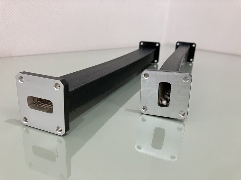
Key Factors That Change the Price
The most immediate cost driver is the frequency band and the corresponding physical size of the waveguide. A smaller cross-section, required for higher frequencies, demands more precise manufacturing tolerances, often within ±0.05 mm. Producing a WR-10 waveguide for 75-110 GHz is inherently more expensive than a larger WR-137 for 5.85-8.20 GHz due to the increased difficulty in forming and plating the tiny, 2.54 mm x 1.27 mm interior channel. This precision machining can increase production time by 30-50%. Following size, the choice of core material and plating creates a major price divergence. Standard models often use phosphor bronze with a 3-5 micron silver plating, costing approximately 15% less than equivalent models. However, applications requiring superior performance or resistance to corrosion, like in naval systems with 95% humidity and salt spray environments, will specify beryllium copper for its better spring properties and a thicker 7-10 micron gold plating. This material upgrade alone can add 40-60% to the base cost, as gold plating is a slower, more controlled process with a higher raw material expense.
A relaxation from a specification of 0.05 dB/meter to 0.10 dB/meter at the center frequency can reduce the price by 20-30%, as it allows for the use of less expensive plating and a more forgiving manufacturing process. Similarly, the power handling rating has a direct correlation. A unit rated for 5 kW of average power needs more robust construction, potentially a larger outer diameter and enhanced cooling features, compared to a 500 W unit, increasing its material mass and cost by at least 25%. Another significant but often overlooked factor is the operating environment specification. A standard waveguide for lab use at 20°C is relatively inexpensive. However, requiring an operational temperature range of -55°C to +125°C, coupled with specifications for pressure windows (to maintain pressure at 10,000 feet altitude) or hermetic seals (to prevent moisture ingress with a leakage rate of less than 1×10⁻⁸ cc/sec), adds complex assembly steps, specialized testing, and additional components. Each environmental requirement can add 15-25% to the unit cost, and in combination, they can easily double it.
| Factor | Lower Cost Example | Higher Cost Example | Approximate Price Impact |
|---|---|---|---|
| Frequency/Size | WR-137 (5.85-8.20 GHz) | WR-10 (75-110 GHz) | +100% to +300% |
| Plating Material | Silver, 3μm | Gold, 8μm | +40% to +60% |
| Attenuation Spec | 0.10 dB/meter | 0.03 dB/meter | +50% to +100% |
| Temperature Range | 0°C to +70°C | -55°C to +125°C | +25% to +50% |
| Order Quantity | 1-2 units (Prototype) | 500+ units (Production) | -35% to -50% per unit |
Placing an order for 1,000 units allows the manufacturer to amortize these fixed costs over a larger batch, often leading to a unit cost reduction of 35-50%. The lead time is also a negotiable factor. A standard lead time of 10-12 weeks is typical. Requesting an expedited delivery in 3-4 weeks usually incurs a 15-25% premium for overtime labor and expedited shipping of raw materials. Therefore, balancing your performance requirements against these commercial factors is essential for optimizing the final price and ensuring you are not over-specifying for your application, which can unnecessarily consume over 50% of your component budget.
How to Check for Good Quality
While datasheets provide essential specifications like 0.07 dB/m loss, true quality is verified through physical inspection and performance testing. A 15-20% failure rate in early production batches is not uncommon for new suppliers, making a rigorous incoming inspection process your primary defense. This involves a multi-stage check, starting with a basic visual and dimensional examination and progressing to electrical verification with a vector network analyzer (VNA). The goal is to correlate the physical attributes you can measure—like a smooth, 8-micron thick gold plating—with the electrical performance you require, such as a Voltage Standing Wave Ratio (VSWR) of less than 1.25:1 across the entire 18-26.5 GHz band.
Check that the mounting holes are cleanly drilled and that the flange surface is perfectly flat, with a flatness tolerance better than 0.05 mm, to prevent signal leakage. A rough or pitted surface indicates poor machining. Gently flex the waveguide through its advertised minimum bend radius, which is typically 5 times its width (e.g., a 50 mm radius for a 10 mm wide waveguide). It should bend smoothly without any binding or creaking noises. When released, it should spring back to its original straight shape with over 95% recovery; any permanent deformation suggests a weak or poorly tempered core material.
The most reliable indicator of quality is a certified test report from a calibrated Vector Network Analyzer. Always request this data for your specific unit, not a generic report. Key metrics to scrutinize are Insertion Loss (IL) and Return Loss (RL). For a 30 cm long WG-14 waveguide, the IL should be less than 0.04 dB at the center frequency, and the RL should be better than 20 dB (equivalent to a VSWR under 1.22). The plot should be smooth, with no sudden dips or peaks exceeding ±0.5 dB, which indicate internal reflections or imperfections.
The two key graphs you need to analyze are the S-Parameter plots for S21 (Insertion Loss) and S11 (Return Loss). The Insertion Loss should be consistently low across the entire frequency band. For instance, a 1-meter long WR-75 waveguide should show a loss of less than 0.10 dB from 10 to 15 GHz. A sudden increase in loss of more than 0.02 dB at a specific frequency often points to an internal deformity or a plating flaw. The Return Loss, which measures how much signal is reflected back to the source, should be high (typically >18 dB). A low Return Loss, say below 15 dB, indicates a poor impedance match, often caused by damaged flange mating surfaces or a deviation in the waveguide’s internal dimensions beyond the ±0.07 mm tolerance. Finally, if your application involves high power, above 1 kW, you should inquire about the manufacturer’s power testing procedure.
Finding and Comparing Suppliers
Identifying the right supplier for flexible waveguides is a critical step that directly impacts your project’s performance, budget, and timeline. The global supplier landscape is diverse, ranging from large multinational corporations with 20-week lead times to specialized workshops capable of delivering prototypes in 3 weeks. A disciplined sourcing process can reduce procurement costs by 15-30% and decrease the risk of project delays by over 50%. The goal is not to find the cheapest option, but to identify the partner whose capabilities, quality control, and pricing structure best align with your specific technical requirements and commercial constraints, whether you need 5 units for R&D or 5,000 for production.
Your search should begin by casting a wide net across different supplier tiers. Start with these primary channels:
- Large Established Manufacturers: Companies with over 50 years in business, like Microtech or Smiths Interconnect, offer extensive product ranges covering frequencies from 2 GHz to 330 GHz. They provide high reliability, with a typical product failure rate of less than 0.5%, but their minimum order quantity (MOQ) can be 10 units and lead times often extend 12-16 weeks. Their pricing is typically 20-40% higher than smaller competitors.
- Specialized Mid-Sized and Regional Suppliers: These firms, often with 50-200 employees, compete on specific technologies like extreme environment waveguides (e.g., -55°C to 200°C range). They often have more agile processes, with lead times of 6-8 weeks and lower MOQs, sometimes even accepting single-unit prototype orders. Their quality can be on par with large manufacturers, but requires more diligent verification.
- Online Component Distributors: Platforms like Digi-Key or Mouser are useful for sourcing standard, off-the-shelf components like WR-90 waveguides. Inventory can fluctuate, and prices may be 15% higher than buying direct, but they offer speed, with delivery in 2-5 days for in-stock items.
Once you have a list of 5-10 potential suppliers, a structured comparison is essential. Create a simple scoring matrix with weighted criteria. Assign a weight of 30% to technical capability and quality. This includes reviewing their ISO 9001:2015 certification status and, more importantly, their test procedures. Do they provide a certified VNA test report with every unit, showing actual S-parameters? A key question to ask is the percentage of units that typically meet the specified Insertion Loss tolerance; a reputable supplier will have a yield of 98% or higher. Assign another 30% weight to cost and lead time. Don’t just compare the unit price for a quantity of 1. Request formal quotations for your exact projected volumes—e.g., 3 prototypes, a pilot run of 50, and a full production order of 500. The price for 500 units should be 25-40% lower than the prototype price. Scrutinize lead times: a quote of 4 weeks for prototypes and 10 weeks for production is standard; anything significantly shorter may indicate cutting corners.
Smart Tips for Getting a Good Price
The unit cost for a standard WR-90 waveguide can vary by over 300%—from 800—based solely on howyou procure it. A strategic procurement plan can consistently achieve savings of 15-40% without compromising the component’s 10-year operational lifespan.
Your first and most powerful lever for cost reduction is to critically review your performance requirements. Negotiating a relaxation of non-critical specifications can lead to immediate savings of 20-30%. For example:
- Relaxing the operational temperature range from a military-grade -55°C to +125°C to a commercial-grade -10°C to +70°C can reduce cost by 15-20%.
- Accepting a standard attenuation specification of 0.08 dB/meter instead of a premium 0.05 dB/meter can save another 10-15%.
- Specifying a standard silver plating (3-5 µm) instead of gold plating (7-10 µm), if the environment permits, can cut material costs by 25-40%.
The single most effective action for lowering your per-unit cost is to consolidate your demand and increase order volume. Manufacturers’ pricing is heavily influenced by economies of scale. A one-off prototype unit bears the full cost of setup, quality assurance paperwork, and engineering review. If you place an order for 5 prototype units instead of 1, the unit price can drop by 15-20% as the fixed costs are amortized. A production order for 250 units will typically be priced 35-50% lower than the prototype unit. To leverage this without over-committing, discuss a tiered pricing model with the supplier. For example, agree on a price for an initial order of 50 units, with a pre-negotiated, lower price that triggers automatically when you place a subsequent order for 500 units within the next 12 months.
A Simple Plan for Your Purchase
A well-executed plan, from initial specification to final delivery, typically spans 8 to 12 weeks and can prevent up to 90% of common issues like incorrect parts or budget overruns. By breaking down the process into four distinct phases—Definition, Sourcing, Validation, and Scale-Up—you can systematically control risk.
| Phase | Key Activities | Timeline | Success Metrics & Checks |
|---|---|---|---|
| Phase 1: Definition & Specification | Finalize technical specs (freq, power, temp); Create a 10-point requirement checklist; Set a budget with a 15% contingency. | 1-2 Weeks | A signed-off specification sheet; A clear go/no-go decision point for proceeding. |
| Phase 2: Supplier Sourcing & Prototyping | Identify 3-5 suppliers; Issue a detailed RFQ; Order 2-3 prototype units from the top 2 candidates. | 3-4 Weeks | Received prototypes with full test data; A comparative cost analysis completed. |
| Phase 3: Validation & Test | Perform incoming inspection; Electrically test prototypes with a VNA; Run an environmental stress test on 1 unit. | 2-3 Weeks | Prototype meets all key specs (e.g., VSWR <1.25:1); Validation report approved by engineering. |
| Phase 4: Production Order & Ramp-Up | Negotiate final price based on volume (e.g., 500 units); Place order with staggered deliveries; Implement a 5% AQL on first production batch. | 4-6 Weeks | Successful integration of first 50 production units; 0% failure rate in the initial batch. |
Critical Checkpoint: Before moving from Phase 2 (Prototyping) to Phase 3 (Validation), hold a formal review. The decision to invest 5,000 in prototype testing should only be made after confirming the units have passed a basic dimensional and visual inspection and the supplier has provided certified VNA reports. This gate prevents wasting 3 weeks of test time on obviously non-conforming parts.
Begin with Phase 1: Definition & Specification. This is the most critical step to avoid cost overruns. Hold a 1-hour meeting with all stakeholders (RF design, mechanical engineering, procurement) to create a “Must Have” vs. “Nice to Have” list. The “Must Haves” are your non-negotiable specs: frequency range (e.g., 33-50 GHz), power handling (1 kW average), and operating temperature (-40°C to +85°C). The “Nice to Haves” are areas for cost negotiation, such as a gold plating versus a silver plating, or a minimum bend radius of 4x width instead of 5x. Formalizing this list prevents scope creep and gives procurement clear negotiating boundaries. Simultaneously, establish a budget with a 10-15% contingency for unforeseen costs, which almost always arise in complex RF projects.
Once you have prototypes in hand, Phase 3: Validation & Test is your quality firewall. Do not assume the supplier’s test report is fully representative of every unit. Plan to spend 2-3 days testing the 2-3 prototype units you received. Use a calibrated VNA to measure the S-parameters of each unit across the entire frequency band. The results should have a standard deviation of less than 0.01 dB between units to ensure consistency. Subject one unit to a simple environmental stress test, such as 50 cycles of flexing to its minimum bend radius and back, then re-measure the VSWR. A change of more than 2% indicates poor mechanical durability.


