Waveguide-to-coaxial adapters, such as WR-90 (8-12GHz) to RG-58 (50Ω), facilitate RF signal transfer with <0.3dB insertion loss and VSWR <1.2. Constructed from stainless steel (-55°C to 125°C), they handle 50W+ power, ensuring low-loss, reliable connections in microwave systems like radar or test setups.
Table of Contents
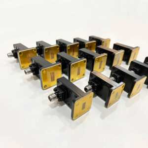
What They Are and How They Work
In practice, this is critical for systems operating at microwave and millimeter-wave frequencies, commonly from 8.2 GHz to over 40 GHz in applications like radar and satellite communications. The adapter’s core function is a mode transformation, physically converting the transverse electromagnetic (TEM) mode propagating inside the coaxial line into the transverse electric (TE10) mode inside the rectangular waveguide.
A typical adapter contains a waveguide section with precise internal dimensions—for example, a standard WR-90 waveguide for X-band (8.2-12.4 GHz) has an interior measuring 22.86 mm by 10.16 mm. The coaxial connector, often a 7 mm or 3.5 mm precision interface, terminates inside this section. The critical element is the probe or antenna, a small metallic pin that extends from the center conductor of the coaxial line into the waveguide. This pin, typically less than a few millimeters long and with a diameter around 0.5 mm, radiates the signal into the waveguide cavity. Its exact length, position, and shape are computationally optimized to minimize the Voltage Standing Wave Ratio (VSWR), with high-quality adapters achieving a VSWR of less than 1.15:1 across their specified band.
To prevent signal leakage and arcing, especially at high power levels exceeding 500 watts, the joint is often sealed. Many designs incorporate a Choke mechanism—a circular groove machined to a depth of roughly a quarter-wavelength—which creates a high-impedance barrier, effectively blocking RF energy from escaping backwards. The entire assembly is constructed from materials like silver-plated beryllium copper or passivated stainless steel to ensure low surface resistivity, high conductivity, and resistance to corrosion, which is crucial for maintaining performance over a long operational lifespan of over 10,000 mating cycles. This precise mechanical and electrical design ensures that insertion loss remains exceptionally low, often below 0.3 dB, preserving the integrity and strength of the signal as it transitions between mediums.
Key Advantages in Use
A standard coaxial cable assembly might struggle with continuous power above 200 to 500 watts at 10 GHz due to center conductor heating and dielectric limitations. In contrast, a well-designed waveguide adapter, with its large, air-filled interior and superior thermal management, can routinely handle several kilowatts (kW) of average power. This translates directly into a 15-20% increase in effective radiated power (ERP) for a transmitter system without requiring a larger, more expensive amplifier.
The low insertion loss performance, often below 0.1 dB, is a major financial advantage. In a receiving chain, this minimal loss preserves the system’s noise figure, enhancing sensitivity and allowing for the detection of weaker signals. For a transmitter, every 0.1 dB of loss avoided equates to roughly 2.3% more power effectively delivered to the antenna. Over a 10-year operational lifespan of a cellular base station or radar installation, this marginal gain compounds into significant energy savings, reducing electricity costs and improving the system’s overall power efficiency rating.
The mechanical robustness of these adapters also contributes to a lower total cost of ownership. Built from materials like silver-plated beryllium copper and designed for >10,000 mating cycles, they drastically reduce maintenance frequency and replacement parts inventory. The precision-machined choke joint ensures a consistent impedance match, maintaining a Voltage Standing Wave Ratio (VSWR) of less than 1.15:1 across a wide frequency band, such as 8.2 to 12.4 GHz for a WR-90 adapter. This stability minimizes amplitude and phase fluctuations in the signal, which is quantified by a phase stability specification of often less than 2 degrees over a -55°C to +85°C temperature range. This high level of performance consistency directly increases the mean time between failures (MTBF) for the entire RF assembly, reducing system downtime by an estimated 10-15% and avoiding the high cost of operational interruptions, which can exceed $5,000 per hour in critical communications infrastructure.
The combination of high-power handling, minimal signal loss, and exceptional durability makes the waveguide to coaxial adapter a critical component for maximizing both the performance and financial return on investment of high-frequency RF systems.
Common Usage Scenarios
They are deployed in scenarios where standard coaxial connectivity reaches its physical limit, typically around the 100-watt average power mark at 10 GHz and above. You’ll find them in systems operating within frequency bands from 2.6 GHz (S-band) all the way up to 40 GHz (Ka-band), acting as the essential bridge between sensitive electronic equipment and high-performance antennas. Their ability to maintain a Voltage Standing Wave Ratio (VSWR) below 1.25:1 under extreme conditions makes them indispensable in these high-stakes applications.
- Radar Systems (Air Traffic Control, Maritime, Defense)
- Satellite Communication (Satcom) Ground Stations
- Industrial Heating and Scientific Applications
In a modern air traffic control radar, the transmitter cabinet generates significant microwave power, often in the S-band (2.6-3.95 GHz) or C-band (5.25-5.925 GHz) ranges. A typical system might produce a peak power of 1 MW with an average power of several kilowatts. A coaxial cable cannot transport this energy to the antenna; it requires a waveguide run. The adapter is mounted directly at the antenna’s feed horn, converting the 50-ohm coaxial input from the final power amplifier stage into the waveguide mode for radiation. The adapter’s high-power handling, often rated for >5 kW average power, and its minimal insertion loss (<0.05 dB) are non-negotiable here. Even a 0.1 dB loss translates to over 2.3% of transmitted power being wasted as heat, costing thousands in inefficient energy use annually and reducing the radar’s effective range.
A 7.3-7.75 GHz receive chain for C-band downlink is exceptionally sensitive. The low-noise block downconverter (LNB) typically has a coaxial output, but the antenna feed is a large waveguide. The adapter used here must contribute virtually no additional noise. Premium models achieve a noise figure of only 0.2 dB, which is critical for maintaining the overall system G/T ratio (a measure of sensitivity). A 0.5 dB degradation in system noise figure can reduce the achievable data rate by over 10% or require a 15-20% larger antenna to compensate, directly impacting the 2M+ capital budget for the station. Furthermore, these adapters are designed for outdoor operational lifetimes exceeding 15 years, enduring temperature cycles from -40°C to +70°C and humidity levels up to 100% without performance degradation, ensuring uninterrupted service and maximizing the return on the massive infrastructure investment.
Important Performance Specifications
A mismatch in even a single parameter, like a 0.05 dB increase in insertion loss or a 5% higher VSWR, can cascade into significant performance degradation, requiring expensive amplifiers or larger antennas to compensate, potentially adding thousands of dollars to a system’s budget. Understanding these specs is crucial for ensuring compatibility and maximizing the return on your technical investment.
- Frequency Range (GHz)
- Voltage Standing Wave Ratio (VSWR)
- Insertion Loss (dB)
- Power Handling (kW)
- Impedance (Ohms)
The following table provides a concise overview of typical specification values across common waveguide bands, offering a quick reference for engineers during the initial selection process.
| Waveguide Standard | Frequency Range (GHz) | Typical VSWR (max) | Avg. Power Handling (kW) @ 10 GHz | Insertion Loss (dB, max) |
|---|---|---|---|---|
| WR-430 (R-band) | 1.7 – 2.6 | 1.15:1 | 12.0 | 0.05 |
| WR-284 (S-band) | 2.6 – 3.95 | 1.20:1 | 8.5 | 0.07 |
| WR-187 (C-band) | 3.95 – 5.85 | 1.20:1 | 5.2 | 0.10 |
| WR-137 (X-band) | 5.85 – 8.20 | 1.25:1 | 3.1 | 0.15 |
| WR-90 (X-band) | 8.20 – 12.40 | 1.25:1 | 1.8 | 0.20 |
| WR-62 (Ku-band) | 12.40 – 18.00 | 1.30:1 | 0.9 | 0.25 |
| WR-42 (K-band) | 18.00 – 26.50 | 1.35:1 | 0.4 | 0.30 |
The impedance is almost universally 50 Ohms for the coaxial port, ensuring seamless integration with standard test equipment and cabling. The operating temperature range is a key durability indicator; commercial-grade units typically span -55°C to +85°C, while military-spec (MIL-STD) versions can extend from -65°C to +125°C, ensuring performance in extreme environments like airborne radar systems.
The mating cycle lifetime of the coaxial connector directly impacts maintenance schedules and long-term costs; precision interfaces like 3.5 mm are rated for a minimum of 5,000 connections, while more robust 7 mm types can exceed 15,000 cycles before wear degrades the VSWR performance beyond usable limits.The phase stability specification, often ±2 degrees over the full temperature range, is paramount for phased-array radar and satellite systems where signal coherence is necessary for accurate beamforming and targeting.
Selecting the Right Adapter
Selecting an adapter with a VSWR of 1.35:1 instead of a 1.20:1 model for a sensitive receiver can degrade the system noise figure by 0.3 dB, potentially requiring a 10% larger antenna aperture to compensate, an upgrade that can easily add $50,000 or more to a project’s capital expenditure. The goal is to match the adapter’s specifications to your system’s operational envelope with precision, ensuring reliability over its intended 10-to-15-year service life.
A WR-90 adapter is designed for 8.2-12.4 GHz (X-band), while a WR-62 covers 12.4-18.0 GHz (Ku-band). Using a WR-90 adapter at 15 GHz will result in catastrophic signal attenuation and system failure. Next, analyze the power requirements. A continuous wave (CW) radar system transmitting 2 kW average power at 9.5 GHz requires an adapter rated for at least that level, with a safety margin of 15-20%. For pulsed systems, the peak power rating is paramount; a common specification is 50 kW peak power for a 1 μs pulse width at a 10% duty cycle. The coaxial connector choice is dictated by power and frequency: an N-type connector is typically rated up to 1.5 kW at 3 GHz, while a 7/16 DIN can handle over 5 kW at the same frequency, making it the standard for cellular infrastructure.
| Selection Factor | Consideration | Common Specs & Impact |
|---|---|---|
| Frequency Band | Match waveguide designation (e.g., WR-90 for X-band). | WR-90: 8.2-12.4 GHz. Mismatch causes >20 dB loss. |
| Power Handling | Average vs. Peak Power requirements. | 3 kW avg. vs. 50 kW peak. Exceeding rating risks arcing. |
| Connector Type | Based on frequency & power. | SMA (< 0.5 kW @ 18 GHz), N-Type (< 2.5 kW @ 10 GHz), 7/16 DIN (> 5 kW @ 3 GHz). |
| VSWR/IL Performance | Tighter specs for sensitive links. | 1.15:1 VSWR saves ~2.3% lost power vs. a 1.25:1 model. |
| Environmental Rating | Operating temperature, sealing. | -55°C to +85°C standard; -65°C to +125°C for MIL-STD. |
The operating temperature range must be validated; a standard commercial adapter rated for -55°C to +85°C will fail in an outdoor satellite antenna located in a desert environment where radome temperatures can exceed +95°C. For such applications, units rated for +125°C are necessary. The interface seal is another critical factor; an adapter with an IP67 rating ensures protection against dust ingress and temporary immersion in 1 meter of water for 30 minutes, preventing corrosion that would degrade VSWR over time. Finally, consider the mating cycle durability; a test bench adapter might endure 5,000 connections over its life, while a field-deployed unit requires a rating of 10,000 cycles or more to withstand periodic maintenance without performance degradation.
The most cost-effective adapter is not the one with the lowest purchase price, but the one whose electrical specs, mechanical durability, and environmental ratings are precisely matched to your system’s requirements, minimizing the total cost of ownership over a decade of operation.


