
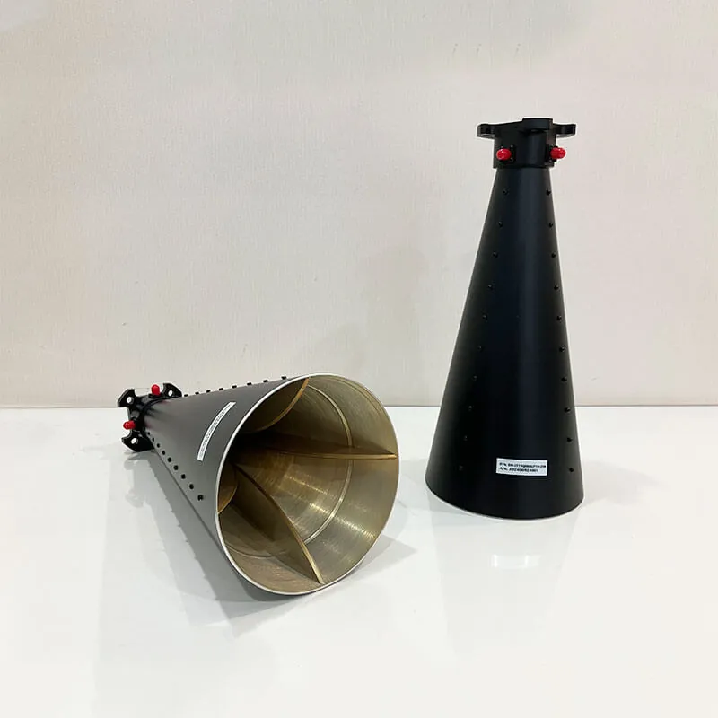
2.0-18.0GHz Wideband Quad-Ridged Antenna
The 2. 0-18. 0GHz broadband four-slot horn antenna is designed for radar and electromagnetic compatibility (EMC) applications. It operates across a wide frequency range, making it ideal for ultra-wideband communication systems. This high-performance antenna offers excellent impedance matching, high gain, and a stable radiation pattern suitable for diverse applications.
Model DH-2T18QRHACP10-2SK
2.0–18.0 GHz Wideband Quad-Ridged Antenna
Designed for broadband RF measurement and system integration, this quad-ridged horn antenna combines wide frequency coverage, horizontal and vertical linear polarization, two SMA female interfaces and a lightweight aluminum structure.
Electrical and Mechanical Data
Use the following published values for preliminary antenna selection. Final project requirements should be confirmed in the approved quotation and technical documentation.
| Frequency Range | 2.0-18.0 GHz |
|---|---|
| Gain | 5-15 dB |
| Polarization | HLP + VLP |
| VSWR (Max.) | 2.5:1 |
| Isolation | 20 dB |
| Connector Type | 2-SMA-Female 50Ω |
| Material | Aluminum |
| Finish | Conductive Oxidation |
| Size | 140*285 mm |
| Net Weight | 1.2 KG |
| Outside Finish | Anticorrosion Blue Paint |
Four-Slot Horn Design
Design
The antenna features a four-slot horn structure that enhances impedance matching and minimizes return loss via an optimized feed design, including a tapered cavity and waveguide transition. Its arc aperture design improves high-frequency radiation patterns, addressing common issues in traditional broadband antennas. Additionally, it supports dual-polarization for versatile applications.
The four-ridge arrangement provides two orthogonal RF signal paths corresponding to horizontal and vertical linear polarization. This configuration allows polarization selection or comparative measurement without replacing the complete antenna assembly.
Broadband Transition
The tapered cavity and waveguide transition support broadband impedance behavior across the published operating range.
Dual RF Ports
Separate SMA female interfaces provide horizontal and vertical linear-polarization signal paths.
Aluminum Construction
Aluminum construction, conductive oxidation and anticorrosion paint support mechanical durability and surface protection.
RF Interface and Installation Considerations
Review the full operating band, cable arrangement, mounting position and available mechanical space before integrating the antenna into a test system or platform.
HLP and VLP Configuration
The published HLP + VLP configuration provides horizontal and vertical linear polarization through separate ports. Confirm the required port assignment and measurement configuration before installation.
Two SMA Female Connectors
The antenna uses two SMA female 50Ω interfaces. Cable loss, adapter loss, connector access and cable bend radius should be included in the complete system review.
Mechanical Envelope
The published size is 140*285 mm and the net weight is 1.2 KG. Installation planning should include horn-aperture clearance, rear connector access and mounting-fixture space.
Project-Specific Requirements
Where size, weight, mounting arrangement or documentation must be adapted to a specific platform, provide the installation drawing and acceptance requirements during quotation.
Published Drawings and RF Data
The available specification PDF provides supporting information for preliminary product review, including mechanical dimensions and published RF performance data.
Typical Wideband Antenna Applications
Application
The antenna’s broadband characteristics and dual-polarization features make it ideal for radar system feeds and EMC testing requiring high-gain performance. Designed with advanced simulation software like HFSS and CST Microwave Studio, its effectiveness is optimized during development. However, for real-world applications, adjustments in size and weight may be necessary to accommodate various installation environments.
Radar System Feeds
Broadband feed configurations requiring horizontal and vertical linear polarization.
EMC and EMI Testing
Laboratory and chamber setups requiring broadband transmission or reception.
Surveillance Equipment
Wide-frequency monitoring arrangements using selectable linear polarization.
Antenna Measurement
Gain and radiation-pattern measurement systems covering multiple microwave bands.
Information to Confirm Before Ordering
Include the following information in your inquiry so the antenna configuration can be reviewed against the intended RF system and installation environment.
State the full required frequency band and any priority sub-bands.
Confirm whether HLP, VLP or both antenna ports will be used.
Specify cable, adapter and connector-routing requirements.
Provide mounting space, orientation and fixture information.
State the required drawings, plots and acceptance records.
Provide prototype quantity, production quantity and delivery target.
Wideband Horn Antenna Specification PDF
Download the published specification sheet containing technical parameters, outline drawings, typical VSWR data and antenna radiation patterns.
Discuss Your Wideband Antenna Requirements
Dolph Microwave offers a high-quality line of wideband quad-ridged antennas for EMI testing, surveillance equipment, and antenna gain measurement. Get linearly polarized antennas with high gain and low VSWR. Contact us today to discuss your needs with our sales engineers.







